43
Section 4 - Owner Serviceable Items
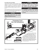
TESTING SOLENOID
WARNING
Do not attempt service on the solenoid without
first disconnecting the electrical power at the
main power source.
1. Remove the screws securing the draft enclosure
cover; then remove the cover.
CAUTION
Solenoid may be hot.
2. Carefully disconnect the two wire leads connected
to the left side of the solenoid by gently pulling and
moving them from side to side.
3. Using a multimeter set to Ohms, test the solenoid's
resistance by touching the meter leads to the solenoid
terminals.
4. If the multimeter reading is between 15 and 30 Ohms,
the solenoid is good. If the multimeter reading is less
than 15 Ohms or more the 30 Ohms, the solenoid is
faulty and should be replaced.
5. If the solenoid is good, carefully attach the wire leads
onto the solenoid terminals (white wire connected to
the upper terminal).
6. Install the cover and secure with the screws.
7. Turn the Power Disconnect Switch to the ON
position.
REPLACING SOLENOID
WARNING
Do not attempt service on the solenoid without
first disconnecting the electrical power at the
main power source.
1. Remove the screws securing the draft enclosure
cover; then remove the cover.
CAUTION
Solenoid may be hot.
2. Carefully disconnect the two wire leads connected
to the left side of the solenoid by gently pulling and
moving them from side to side.
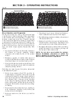
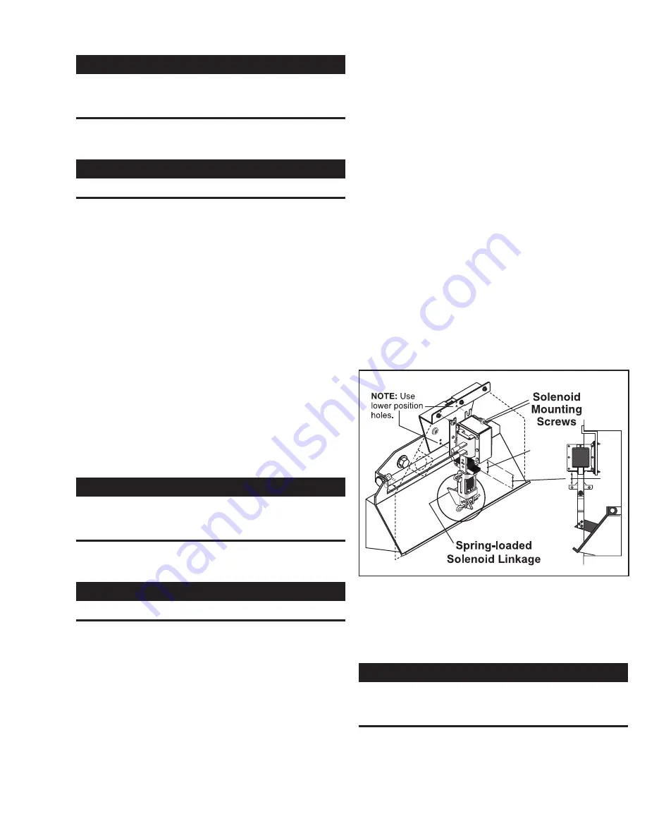
3. Remove the top cotter key of the linkage.
4. While supporting the solenoid with your hand,
remove the top two solenoid mounting screws and
loosen the bottom two.
5. Lift up on the solenoid until it clears the screw heads
and remove.
6. Place the new solenoid into position and lightly
secure with the screws. Adjust the solenoid up
or down until the solenoid plunger free length is
between 15/16" and 1"; then tighten the screws
securely. Connect the solenoid to the linkage with
the cotter pin. Slightly spread the legs of the cotter
pin. Check that the spring-loaded linkage and
damper door are not binding and that the spring is
not broken or missing.
7. Carefully attach the wire leads onto the solenoid
terminals (white wire connected to the upper
terminal).
8. Install the cover and secure with the screws.
9. Turn the Power Disconnect Switch to the ON
position.
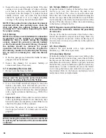
NOTE: If the solenoid rattles during operation,
the alignment between the solenoid and the lift
tab is incorrect. To align the solenoid and lift tab,
loosen the four solenoid mounting screws and
move the solenoid until the solenoid plunger
aligns with the lift tab. Secure the solenoid; then
make sure it operates smoothly.
Fig. 44
Max.
1"
(25 mm)
Max.
1"
(25 mm)
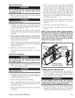
TEMPERATURE CONTROLLER
1. Disconnect the electrical power at the main power
source to the outdoor furnace; then open the control
panel door. Remove the screws securing the inner
door panel; then remove the panel.
WARNING
Do not attempt service inside the electrical
control panel without first disconnecting the
electrical power at the main power source.
2. Carefully label each of the wires connected to the
temperature controller according to the numbered
connections identified on the top of the controller.

