background image

51

Section 6 - General Information

WIRING DIAGRAMS

Summary of Contents for Pallet Burner Dual Fuel

Page 1: ...dealer or heating contractor Record the information below for future reference Model Serial Number Installation Date Dealership Name Phone Number Owner Name p n 9000315 REV A 28 MAY 2015 Pallet Burner Dual Fuel Portland Oregon USA OMNI Test Laboratories Inc Tested Listed By US 117 S 02b 2 IN THE U S THIS APPLIANCE IS FOR NON RESIDENTIAL APPLICATIONS ONLY ...

Page 2: ...ions supplied by the manufacturer 2 FUEL USED Only those listed fuels recommended by the manufacturer of your unit Never use the following trash plastics gasoline rubber naphtha garbage material treated with petroleum products particle board railroad ties and pressure treated wood leaves paper products and cardboard 3 LOADING FUEL For a more efficient burn pay careful attention to loading times an...

Page 3: ...Water System Installations 23 Water to Water Heat Transfer System 23 Vented System Installation 24 Direct Circulation Baseboard Installation 25 Radiant Floor System Installations 26 Pool and or Hot Tub Heating 29 FINALIZING THE INSTALLATION 30 FILLING OUTDOOR FURNACE WITH WATER AND PURGING AIR 30 SECTION 2 OPERATING INSTRUCTIONS 32 Wood Selection and Preparation 32 FIRING THE FURNACE 33 FILLING TH...

Page 4: ... 4 Owner Serviceable Items Section 5 Troubleshooting Section 6 General Information Anyone owning or operating this outdoor furnace must read fully understand and follow all of the information in this manual and the accompanying gas or fuel oil burner Operator s Manual NOTE In higher populated areas extend the chimneytoaheightabovetheroofsofsurrounding buildings see Outdoor Wood Furnace Best Burn P...

Page 5: ...aining water from the outdoor furnace If the water in the outdoor furnace ever boils be sure to check the water level and restore to full If water is added the proper level of Corrosion Inhibitor Plus p n 1650 must be maintained WARNING When cleaning the outdoor furnace be careful not to spill any coals WARNING ALWAYS store ashes in a covered non combustible container WARNING When installing a hea...

Page 6: ...tial fire NOTE This outdoor furnace is not to be used with an automatic stoker WARNING When adding wood to the firebox be careful not to get pinched between the wood and the door frame or any part of the outdoor furnace Use extreme care with large pieces of wood that may be difficult to handle NOTE The sight gauge valve should always be closed except when checking water level Water will automatica...

Page 7: ...or walking INSTALLATIONS IN MASSACHUSETTS 1 All installation components must be products approved in the Commonwealth of Massachusetts by the Gas and Plumbing Board 2 The maximum run of tubing from the water heater to a fan coil is 50 linear feet 3 Persons operating this hydronic heater are responsible for operation of the hydronic heater so as not to cause a condition of air pollution as defined ...

Page 8: ...TION INFORMATION Foundation The Pallet Burner outdoor furnace must be installed on a concrete foundation Refer to Fig 4 for dimensions and for the location of the hollowed out area A 4 to 6 thick concrete slab works well however a thicker slab may be used to obtain the desired door opening height If the area for the concrete slab is unstable and or affected by frost heaving consider installing 2 c...

Page 9: ... the outdoor furnace see Water Quality and Maintenance Corrosion Inhibitor Plus To aid in protecting the system from corrosion it is imperative to add Central Boiler Corrosion Inhibitor Plus p n 1650 For recommended initial treatment rates refer to Water Quality and Maintenance When initially filling the system see Finalizing the Installation add the Corrosion Inhibitor Plus before adding water to...

Page 10: ...can greatly increase the fuel consumption NOTE If it is unavoidable that the trench will run through an area of ponding water use ThermoPEX instead of other materials ThermoPEX should also be used for above ground or winter installations and if the area is likely to be affected by compaction Temporary Above Ground or Winter Installations For temporary above ground or winter installations in which ...

Page 11: ... allow pressure testing of both supply and return lines Pressurize with 50 psi 3 5 kg cm2 of air then check after 30 minutes to see if pressure has dropped A drop in pressure indicates a leak repair as necessary 6 Connect the supply and return lines to the outdoor furnace and the existing heat emitter s Fig 7 shows some of the PEX fittings and tools used in making connections Fig 7 CAUTION Allow f...

Page 12: ... Flow For a single building water to air heat exchanger system with a domestic water heater the direction of water flow must go from the hot outlet on the outdoor furnace to the lower side fitting of the domestic water heater exchanger to the lower fitting of the heat exchanger in the plenum of the existing furnace and then to the return port of the outdoor furnace NOTE Some systems may have diffe...

Page 13: ...lation pump s must be installed in the supply line s with the arrow on each pump pointed away from the outdoor furnace In order to avoid circulation problems do not install the pump s in the return line s The pump s s must be located near the base of the outdoor furnace if the system has a high flow pump or very low resistance on the outlet side of the pump For example if the outdoor furnace is 20...

Page 14: ...ves illustrated throughout the manual may vary from your installation See the installation instructions provided with the thermostatic valve A thermostatic valve must be installed on each set of supply and return lines in the system to maintain the outdoor furnace water temperature above 150 F 65 C Operating the outdoor furnace with the water temperature less than 150 F 65 C may result in more con...

Page 15: ...15 Section 1 Furnace Installation ...

Page 16: ...tting on the top of the water heater for the hot water heat exchanger NOTE If the water heater has been in service flush the water heater prior to installing the hot water heat exchanger Anode rod residue or other sediments in the water heater may plug the heat exchanger NOTE Some gas water heaters are equipped with a high water temperature probe that is connected to the gas valve When the water t...

Page 17: ...heat exchanger it should be mounted in the center without gaps on the sides that would allow air to flow around the heat exchanger All air must be directed through the face of the exchanger Air flow deflectors need to be installed in the plenum on the outlet side of the heat exchanger if air flow is funneled into the heat exchanger Be sure to consider the airflow through the ductwork so air circul...

Page 18: ... F 85 C minimum NOTE On multi speed fans cap and tape off any extra wires NOTE Installer must comply with all applicable codes and regulations NOTE This configuration allows use of a 24 volt thermostat on older forced air units with no control board NOTE A certified electrician must perform the electrical installation WATER TO AIR HEAT EXCHANGER AND WATER HEATER SYSTEM C R Y G FA N TIM E PRG M RUN...

Page 19: ...p n 255 p n 5349 p n 5348 Optional Copper Fittings not included in kit 116 116 255 117 p n 2441 2491 p n 2443 Installer must comply with all applicable codes and regulations NOTE A pump must be installed in the hot supply line between the outdoor furnace and thermostatic valve Outdoor furnace water temperature setpoint should be set at 185 F minimum NOTE p n 5926 p n 5926 p n 1330 PEX Return Suppl...

Page 20: ...rate if the outdoor furnace is out of fuel Refer to Fig 22 for one possible arrangement 2 An alternative method is to install a line voltage thermostat to control the blower on the forced air furnace In this installation a 120 volt line is run from the thermostat to the forced air furnace One wire is connected to the hot line feed and the other wire is connected to the forced air furnace blower wi...

Page 21: ...without the need for manifolds for mounting of up to three pumps on the outdoor furnace NOTE If a Taco 014 pump is used the pump should be mounted at the base of the outdoor furnace and a 1 1 4 supply line to the pump should be used to ensure adequate supply feed to the pump NOTE If the outdoor furnace is unable to maintain a water temperature of 150 F 66 C or higher inspect the thermostatic valve...

Page 22: ... heaters or panel radiators 2 A water to air heat exchanger with a thermostatic ally controlled fan can be installed in the lower part of the building being heated Fig 24 This can increase the amount of heat added to the building helping to maintain a constant temperature This heat exchanger can be added in the return line of the system after the water to water heat exchanger 3 An additional radia...

Page 23: ...ely 165 F of water temperature transfer The temperature controller on the outdoor furnace may be adjusted to allow the outdoor furnace to reach water temperatures up to 195ºF Each system will vary in water temperature transfer depending upon the heat load of the existing heating system The addition of a wraparound pump with a water to water heat exchanger may increase heat transfer by allowing cir...

Page 24: ...heck or zone valve will prevent thermal circulation and overheating of building It is very important to eliminate all air and water leaks valve packings bleeders etc and purge all air from the existing system 1 After filling the outdoor furnace see Initial Start Up Procedures section and existing system with water purge the air from the indoor system by closing the valves on the outdoor furnace th...

Page 25: ...on baseboard installation examples CAUTION This outdoor furnace is not intended to be the only source of heat This horizontal assembly must not exceed a height of 4 inches 10 cm above top of water heater NOTE Outdoor furnace water temp setpoint should be set at 185 F 85 C minimum Fig 27 Return to Outdoor Furnace This horizontal assembly must not exceed a height of 4 inches 10 cm above top of water...

Page 26: ... spacing of each circuit should be 12 between tubes The water circulates in opposite directions to provide an even distribution of heat The mixing valve regulates the temperature of the water circulating through the loops by mixing return water with the hot supply water In applications where high heat loss is expected loop spacing may be reduced to 10 or less If additional information is desired c...

Page 27: ...27 Section 1 Furnace Installation Fig 30 Fig 31 ...

Page 28: ...28 Section 1 Furnace Installation Fig 32 Fig 33 ...

Page 29: ... heat exchanger may cause severe personal injury death or substantial property damage CAUTION Do not operate the outdoor furnace frequently or for extended periods of time with the water temperature below 150 F 65 C as this will result in more condensation in the firebox that can lead to corrosion Pools and hot tubs typically have high water flow rates from 30 50 gpm 114 189 lpm Because the MP Ser...

Page 30: ...rom the water lines when filling the system Also the circulation pump s must be installed in the hot supply line s NOTE If using the valve on the water heater to fill the outdoor furnace flush the water heater to remove all sediment before filling the outdoor furnace NOTE If the outdoor furnace is being filled with water when the temperature is below freezing circulate the water immediately after ...

Page 31: ...nect hose A and replace caps on valves 1 2 and 3 16 Open the valve on the hot supply line of the outdoor furnace and valve 5 NOTE The valves on the hot supply and return lines of the outdoor furnace and valves 4 and 5 should all be open allowing the pump to circulate heated water in the system Start pump NOTE If there are multiple circuits connected to the outdoor furnace repeat the process for ea...

Page 32: ...not be used Green wood contains about 50 moisture by weight Energy is required to heat the wood and evaporate the moisture energy which could have been used to provide heat The illustration shows that burning drier seasoned wood provides more energy for heating compared with burning green unseasoned wood that uses more energy to evaporate the moisture and provides less energy for heating Unseasone...

Page 33: ...ed in Section 3 CAUTION Failure to clean the firebox as indicated will result in excessive corrosion Periodically during the normal operation of the outdoor furnace look at the water temperature display It should indicate a reading that is within 10 F of the controller setting Areading of 212 F or above indicates either a low water condition or a malfunctioning temperature controller or snap disc ...

Page 34: ...perate the outdoor furnace with the firebox door open Combustion in the firebox cannot be controlled if the firebox door is left open or unsecured If the firebox door is left open an uncontrolled burn will result To return to a controlled burn close and secure the door NOTE Creosoteisanaccumulationofcombustion by products on the surfaces of wood burning appliances Twice a month during the heating ...

Page 35: ... at the beginning of the burn cycle to provide an immediate high temperature combustion helping to reduce visible emissions and creating a secondary combustion of unburned gases The amount of time the auxiliary burner operates may be preset by the operator The timer located within the side panel should be set between 5 and 7 minutes The timer may be set for a longer duration up to 15 minutes if th...

Page 36: ...tructions SECTION 3 MAINTENANCE INSTRUCTIONS SERVICE INTERVAL S e e S e c t i o n N u m b e r B e f o r e f i r s t o p e r a t i o n o f s e a s o n D a i l y W e e k l y M o n t h l y S e m i A n n u a l l y P o s t S e a s o n ...

Page 37: ...rward to prevent the ashes from sealing in moisture on the bottom and along the edges It is especially important to scrape the walls and the four corners at the ash line and below If this maintenance operation is not performed as directed deterioration can result from the moisture trapped between the ashes and the steel 1 Remove any heavy or solidified ashes When ashes build up to either the door ...

Page 38: ...al of ashes Place ashes in a metal container with a tight fitting metal lid It can take many days before the ashes are completely cooled Other waste should not be placed in this container 3 Each time the ashes are cleaned out inspect the door rope see Section 3 5 to make sure it is sealing properly WARNING When cleaning the outdoor furnace be careful not to spill any hot ash outside of the noncomb...

Page 39: ...hat will be used to fill the outdoor furnace softened water is recommended 1 Collect a small sample of the water to be used to fill the outdoor furnace in a clean container 2 Dip the pH test strip from the test kit in the water Shake excess water off the test strip Compare the color of the test strip to the chart provided to determine pH level 3 If the pH level is between 6 5 and 8 and there are n...

Page 40: ...d level of protection NOTE If there is a leak in the system or if the outdoor furnace loses water from boiling frequently the problem should be identified and repaired immediately Under normal operation little or no water needs to be added Adding water to the furnace may cause corrosion if not immediately treated with Corrosion Inhibitor Plus to the proper pH and nitrite levels In addition the amo...

Page 41: ...he firebox and bottom of the water jacket beneath the firebox using a wand placed in the vent Fig 41 CAUTION Completely clean out the firebox before draining water from the outdoor furnace Fig 41 3 Close the drain valve securely and replace the cap on the drain after flushing the outdoor furnace 4 Fill the furnace following the procedure in Water Quality and Maintenance making sure to operate the ...

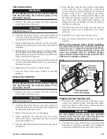
Page 42: ...ntenance 2 Using a scraper remove the firebox door seal rope and clean any remaining silicone adhesive from the groove Any residue left in the groove will interfere with the new seal 4 Apply a 1 4 6 mm diameter bead of silicone sealant into the entire firebox door seal groove 5 Starting at the center of the top side of the firebox door insert the new door seal rope into the groove pressing it firm...

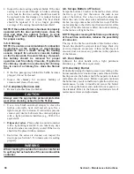
Page 43: ...our hand remove the top two solenoid mounting screws and loosen the bottom two 5 Lift up on the solenoid until it clears the screw heads and remove 6 Place the new solenoid into position and lightly secure with the screws Adjust the solenoid up or down until the solenoid plunger free length is between 15 16 and 1 then tighten the screws securely Connect the solenoid to the linkage with the cotter ...

Page 44: ...r source to the outdoor furnace then open the control panel door Remove the screws securing the access box panel then remove the panel WARNING Do not attempt service inside the electrical control panel without first disconnecting the electrical power at the main power source 2 Disconnect the sensor wires from the controller 3 Using a multimeter set to Ohms touch the meter leads to the wires discon...

Page 45: ...ry restricted remove the firewood and hot coals then check the chimney top and bottom and behind the baffle for obstructions 8 Building s poorly insulated or uninsulated Poorly insulated or uninsulated buildings buildings with uninsulated or poorly insulated ceilings or a lack of proper insulation under radiant flooring can cause excessive fuel consumption and or heating problems 9 Supply and retu...

Page 46: ...re open to allow circulation C SOLENOID DOES NOT OPERATE 1 Fuse blown Check the fuse Check damper and solenoid area for obstructions or damage Be sure the damper door operates properly then replace the fuse 2 Solenoid not operating properly Solenoid may be damaged If so be sure to check the linkage for free movement and for creosote buildup between the damper door and draft opening Replace the sol...

Page 47: ...up to temperature the first time will take a considerable amount of time and wood once warm wood consumption will be reduced if the concrete slab and building are insulated properly The following will also have a high heat demand poorly insulated buildings buildings with large amounts of glass windows doors buildings with overhead doors greenhouses uninsulated crawl spaces outdoor air infiltration...

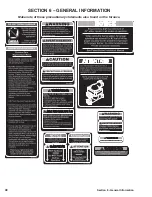
Page 48: ...48 Section 6 General Information SECTION 6 GENERAL INFORMATION Make note of these precautionary statements also found on the furnace ...

Page 49: ...49 Section 6 General Information 1200042 005 10854 011 6170 011 1200198 001 2500053 PARTS LISTING ...

Page 50: ...URNACE MEASUREMENTS A B C D E F G H Pallet Burner 260 70 93 88 78 89 104 4 I 8 Dimension comprend troid sections de cheminée DIMENSIONS DE LA CHAUDIÈRE cm A B C D E F G H Pallet Burner 660 178 236 224 198 226 264 10 I 20 2014 Central Boiler D E F B G H C A I FURNACE MEASUREMENTS ...

Page 51: ...51 Section 6 General Information WIRING DIAGRAMS ...

Page 52: ... damage caused by misuse or abuse unauthorized work alterations to the furnace and normal wear items such as door gasket exterior paint and replaceable chimney parts are not considered warrantable items Components such as aquastats pumps actuators etc that are used on the outdoor wood furnace or in the heating system carry their own warranty provided by their manufacturer Central Boiler is not lia...

Reviews: