


SKU 34542 For technical questions, please call 1-800-444-3353 PAGE 5
13.
WARNING! The warnings and precautions discussed in this manual cannot
cover all possible conditions and situations that may occur. It must be under
stood by the operator that common sense and caution are factors which cannot
be built into this product, but must be supplied by the operator.
SAVE THESE INSTRUCTIONS
impaired while taking drugs. If there is any doubt, do not attempt to use this
product.
10.
Use the right tool for the job. Do not attempt to force a small tool to do the
work of a larger industrial tool. There are certain applications for which this
product was designed. It will do the job better and more safely at the rate for
which it was intended. Do not modify this product, and do not use this product
for a purpose for which it was not intended.
11.
EXPLOSION DANGER! Never overinflate tires or other inflatable items.
When inflating a tire with compressed air, make sure to inflate the tire to
the exact PSI as recommended by the tire manufacturer. Always use a
pressure gauge (not included) to check the actual pressure in tires.
12.
Always dispose of old tires in accordance with local, state, and federal
laws.
UNPACKING
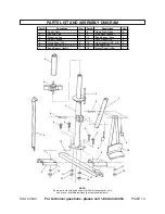
When unpacking, check to make sure all the parts shown on the Parts Lists on page 10
are included. If any parts are missing or broken, please call Harbor Freight Tools at the
number shown on the cover of this manual as soon as possible.
ASSEMBLY INSTRUCTIONS
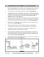
1.
Locate the Hex Bolts (6), Lock Washers (11), Hex Head Nuts (12), Center Post
(1), and the Pedestal Base (13). (See Assy. Diagram.)
2.
Bolt the Pedestal Base (13) to the Center Post (1), using the Hex Bolts (6), Lock
Washers (11), and Hex Head Nuts (12). NOTE: The end of the Pedestal Base
with the triangular stop should be directly in front of the Bead Breaker Handle (7)
and Bead Breaker Shoe (10). (See Assy. Diagram.)
3.
Bolt the two Side Base Channels (9) into place. (See Assy. Diagram.)


