SKU 39955
For technical questions, please call 1-800-444-3353.
Page 10
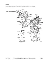
To Adjust the Table
The table rotates 360 degrees and tilts 45 degrees right and left. The table is capable of being raised, lowered
and swiveled about the column.
1)
Raise or lower the Table by slackening off the Arm Locking Handle and turning the crank clockwise to
raise it and counterclockwise to lower it.
2)
The Table can be swiveled about the Column by loosening the Arm Locking Handle. The Table
assembly and Rack move as one around the Table.
3)
You can tilt the Table by loosening the Bevel Table Locking Screw (part #12B and 14B) and tilting the
Table to the desired angle.
The Table is fitted with an Angle Scale to determine the degree of slant. For all normal operations the Table
should be set at 0 degrees. To ensure that the drill is entirely perpendicular to the table, insert a piece of
straight round bar in the chuck, place a Square on the Table and bring it up to the round bar. Adjust the Table
tilt if necessary so that the Table is correctly aligned.
Setting the Drilling Depth
Located near the Spindle Feed Shaft is a Depth Stop Collar (A) (See Figure below) which contains a
graduated scale. The collar is capable of turning around the Shaft, and may be locked in place by a Locking
Screw (B-below). Degrees are measured in both inches and metric.
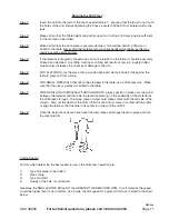
Step 1)
With power OFF, lower the Chuck until the drill contacts the surface of the work piece. Hold it
in that position.
Step 2)
Loosen the Locking Screw and turn the collar so that the measurement for the depth of the
hole required is in line with the Pointer (C).
Step 3)
Lock the Collar in position using the Locking Screw.
The Drill is now set to drill holes to your predetermined depth from that particular starting point.
Figure 3
REV 03c

