background image

SKU 39955 

For technical questions, please call 1-800-444-3353. 

Page 11

Running the Drill Press

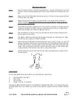
Step 1) 

Insert the drill into the jaws of the chuck approximately 1”, ensuring that the jaws do not touch 
the flutes of the drill.  Before tightening the Chuck, ensure that the drill is centered within the 
jaws.  

Step 2) 

Make certain that the Table height and position is set so that the drill travel range is sufficient 
for the material to be drilled.

Step 3) 

Make certain that the work piece is securely clamped.  It should be held in a drill vise or 
bolted to the table.  Never hold the material with your bare hands while drilling as this may 
result in severe personal injury.

Step 4) 

If the material is irregularly shaped and can not be laid flat on the table, it should be securely 
blocked and clamped.  Any tilting, twisting or shifting will result not only in a roughly drilled 
hole but also increases the chances of damage to the drill.

Step 5) 

FOR FLAT WORK, lay the piece onto a wooden base and clamp it down firmly against the 
table to prevent it from turning.

Step 6) 

FOR SMALL MATERIALS that cannot be clamped to the table, use a drill press vise.  Make 
sure that the vice is clamped or bolted to the table.

Step 7) 

WHEN DRILLING COMPLETELY THROUGH WOOD, always position a piece of scrap wood 
between the material and the table to prevent splintering on the underside of the material as 
the drill breaks through.  The scrap piece of wood must make contact with the left side of the 
column.  Also, set the depth of the drill so that the drill will not come in contact with the table 
or align the table so that the hole in its center is in line with the drill bit.

Step 8) 

Once the instructions above have been followed, make certain guards are in place and turn 
the machine ON.   

Cutting Speeds

Factors which determine the best speed to use in the drill press operation are:

1) 

Type of material to be drilled

2) 

Size of hole

3) 

Type of drill bit

4) 

Quality of the hole or cut desired.

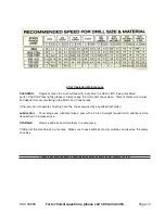
Generally, the SMALLER THE DRILL BIT the GREATER THE REQUIRED RPM.  In soft material, the speed 
should be higher than for hard metals.  As a guide, the drill speed for a given drill bit size is listed in the chart 
below.

REV 03c

Summary of Contents for 39955

Page 1: ...served No portion of this manual or any artwork con tained herein may be reproduced in any shape or form without the express written consent of Harbor Freight Tools Diagrams within this manual may not be drawn proportionally Due to continuing improvements actual product may differ slightly from the product described herein Tools required for assembly and service may not be included For technical q...

Page 2: ...t 1 x 1 2 Warning The warnings cautions and instructions discussed in this instruction manual cannot cover all possible conditions and situations that may occur It must be understood by the operator that COMMON SENSE AND CAUTION ARE FACTORS WHICH CANNOT BE BUILT INTO THIS PRODUCT BUT MUST BE SUPPLIED BY THE OPERATOR The Operator PLEASE REMEMBER Do not operate the product if under the influence of ...

Page 3: ...ed when not in use Keep Guards in place and in working order Do not abuse the power cord Do not yank on cord to disconnect it from outlet Keep the cord away from heat oil and sharp edges Note Performance of this tool may vary depending on variations in local line voltage Extension Cord usage may also affect tool performance Grounding Voltage Warning Common household current is 110 120 volts As lon...

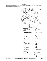
Page 4: ...questions please call 1 800 444 3353 Page 4 E H Unpacking Unpack and check contents Make sure you have all parts described below If any parts are missing or broken please call Harbor Freight Tools at 1 800 444 3353 REV 03c 08l ...

Page 5: ...WG AWG AWG 0 10 0 18 18 16 16 14 14 12 12 10 1 13 0 16 16 14 14 14 12 12 12 13 1 15 14 14 12 12 12 12 12 15 18 14 12 12 12 12 12 Do NOT modify your plug in any way If you have any doubt call a qualified electrician Assembly Your Drill Press will require assembly To assist you with assembly and operation please refer to the Assembly Diagram and Parts List located on pages 14 15 16 and 17 Lay out al...

Page 6: ...mn Step 5 Locate the Rack part 6B and with the smooth end of the Rack pointing upward slide it down through the large round opening in the Table Support part 3B Engage the Rack into the Gear Mechanism found on the inside opening of the Table Support See Figure 2 below Step 6 While holding the Rack and the Table Support as assembled slide both down over the Col umn Slide the Rack down until the Rac...

Page 7: ...ly into position Align the Head with the Base 10B and firmly secure it into position with the Set Screws Screw the three 3 Rods part 19A firmly into the Hub part 20A Chuck Step 1 The Chuck part 30 is to be assembled to the Spindle part 32 according to the follow ing instructions Loosely slide the Chuck onto the Spindle Make certain that the teeth of the Chuck are not exposed Put a piece of scrap w...

Page 8: ...SKU 39955 For technical questions please call 1 800 444 3353 Page 8 Light Bulb Screw a light bulb not more than 60 Watt into the Socket part 48A inside the Head REV 03c ...

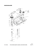
Page 9: ...r Drill Press on page 8 of this manual on both sides of the head Turn the Belt Tension Handle 14A clockwise to bring the Motor Pulley close to the Spindle Pulley which will allow the belts to be moved easily Note Please refer to the Pulley and Spindle Diagram with regard to the following steps Step 2 Lubricate the Idler Pivot Shaft part 4 and the Pulley Idler with light grease and install it in it...

Page 10: ...es To ensure that the drill is entirely perpendicular to the table insert a piece of straight round bar in the chuck place a Square on the Table and bring it up to the round bar Adjust the Table tilt if necessary so that the Table is correctly aligned Setting the Drilling Depth Located near the Spindle Feed Shaft is a Depth Stop Collar A See Figure below which contains a graduated scale The collar...

Page 11: ... it down firmly against the table to prevent it from turning Step 6 FOR SMALL MATERIALS that cannot be clamped to the table use a drill press vise Make sure that the vice is clamped or bolted to the table Step 7 WHEN DRILLING COMPLETELY THROUGH WOOD always position a piece of scrap wood between the material and the table to prevent splintering on the underside of the material as the drill breaks t...

Page 12: ...ulating in the Motor and Chuck areas If the jaws do not operate smoothly have the chuck serviced by a qualified technician Lubrication For average use lubricate twice a year with a 20 to 30 weight household oil Lubricate more frequently with increased use STORAGE Remove drill bits and store them in a safe place Child proof the machine and work area Make sure to use padlocks master switches and rem...

Page 13: ...UYER THAT HE OR SHE IS QUALIFIED TO MAKE ANY REPAIRS TO THE PRODUCT OR THAT HE OR SHE IS QUALIFIED TO REPLACE ANY PARTS OF THE PRODUCT IN FACT THE MANUFACTURER AND OR DISTRIBUTOR EXPRESSLY STATESTHAT ALL REPAIRS AND PARTS REPLACEMENTS SHOULD BE UNDERTAKEN BY CERTIFIED AND LICENSEDTECHNICIANS AND NOT BYTHE BUYER THE BUYER ASSUMES ALL RISK AND LIABILITY ARISING OUT OF HIS OR HER REPAIRS TO THE ORIGI...

Page 14: ... Hex Head M8 1 25A Screw 1 2A Adjusting Lever 1 26A Switch Box 1 3A Motor Bracket Support 1 27A Screw Pan Cr M5 1 4A Motor Mount 1 28A Locking Switch 1 5A Lock Washer 12mm 1 29A Pan Head Screw 1 6A Hex Nut M12 x 1 25 1 7A Motor 1 31A Cover Switch Plate 1 8A Hex Nut M8 1 32A Rocker Switch 1 9A Washer 1 33A Screw Pan Cr M6 1 10A Cord Motor 1 34A Lead 3 1 11A Hex Head Screw M8 1 12A Motor Bracket Sup...

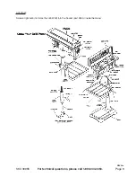
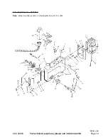
Page 15: ...SKU 39955 For technical questions please call 1 800 444 3353 Page 15 29 30 31 32 33 22 23 24 25 26 27 28 Assembly Diagram 39955 18A 3A 5A REV 05j ...

Page 16: ...SKU 39955 For technical questions please call 1 800 444 3353 Page 16 Assembly Diagram 39955 A Note All part numbers shown in this diagram have an A suffix REV 03c 08l ...

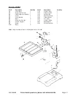
Page 17: ...y Part Description Quantity 1B Collar Rack 1 11B Column Tube 1 2B Screw Hex Soc Set 1 12B Table Lock Pin 1 3B Table Support w Indicator 1 13B Nut hex M8 1 4B Crank 1 14B Hex Head Screw 1 5B Crank Handle 1 15B Table w Scale 1 6B Rack 3 16B Pin Gear 1 7B Screw hex Soc Set 1 17B Column Clamp 1 8B Column Support 1 18B Helical Gear 1 9B Screw 1 19B Worm Elevation 1 10B Base 2 ...

Page 18: ...SKU 39955 For technical questions please call 1 800 444 3353 Page 18 ...

Page 19: ...for incidental contingent special or consequential damages arising from the use of our product Some states do not allow the exclusion or limitation of incidental or consequential dam ages so the above limitation of exclusion may not apply to you This warranty is expressly in lieu of all other warranties express or implied including the warranties of merchant ability and fitness To take advantage o...

Reviews: