SKU 39955
For technical questions, please call 1-800-444-3353.
Page 7
Step 9)
Locate the Column Clamp (part #17B) and insert it into the Table Support. Once inserted,
tighten it by hand. Once this is done, rotate the Worm clockwise with the Crank. If necessary,
loosen the Set Screw in the Crank and reposition the Crank as close to the Table Support as
possible. Tighten the Set Screw.
Step 10)
Check the “gap”, i.e., the clearance between the Table Crank and the Table Support. If the
gap is larger than 1/32”, crank backlash will be minimized.
Head to Column
Step 1)
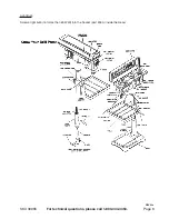
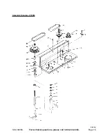
With assistance, slide the Head (part #45A) onto the Column as shown in the Assembly
Diagram. It may be necessary to unscrew the Head Lock Set Screws (part #15A) slightly to
ensure that they do not protrude internally, as this will prevent the head from sliding fully into
position. Align the Head with the Base (#10B) and firmly secure it into position with the Set
Screws. Screw the three (3) Rods (part #19A) firmly into the Hub (part #20A).
Chuck
Step 1)
The Chuck (part #30) is to be assembled to the Spindle (part #32) according to the follow-
ing instructions. Loosely slide the Chuck onto the Spindle. Make certain that the teeth of the
Chuck are not exposed. Put a piece of scrap wood on the table to protect the Chuck nose.
Pull the Spindle down using the Handle. Press the Chuck nose hard against the scrap wood
on the table until the Chuck is forced into a solid fit. The Chuck is pressure fitted.
Pulley Cover Knob
Step 1)
Locate the Knob (part #21) and the pan head screw (part #7). Slide the Knob into the hole in
the front of the Pulley Cover. Twist the screw into the knob from the underside of the Pulley
Cover. Screw on tightly.
Oiler System
Step 1)
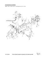
Use four M5x0.8-8 Screws (#51A) to fasten the two Oil Brackets (#50A). Insert the Oil Bottle
with Spigot Assembly (#52A and #53A) into the Oil Brackets.

