background image

Page 7 SKU # 41889

INSTALLING THE SAW BLADE

Your new scroll saw accepts 5” pin-type blades. Your saw is also equipped with blade
adapters that allow you to use a variety of 5” plain-end blades.

WARNING: To prevent personal injury, always disconnect the plug from the power source
before changing blades or making adjustments.

1.

Rotate the blade tension knob counter-clockwise to release blade tension.

2.

Remove the table insert and remove the blade from the upper and lower blade holders by pulling
forward on the blade and then lifting the blade through the access hole in the table. Slight downward
pressure against the upper holder may be helpful when removing the blade from upper holder.

3.

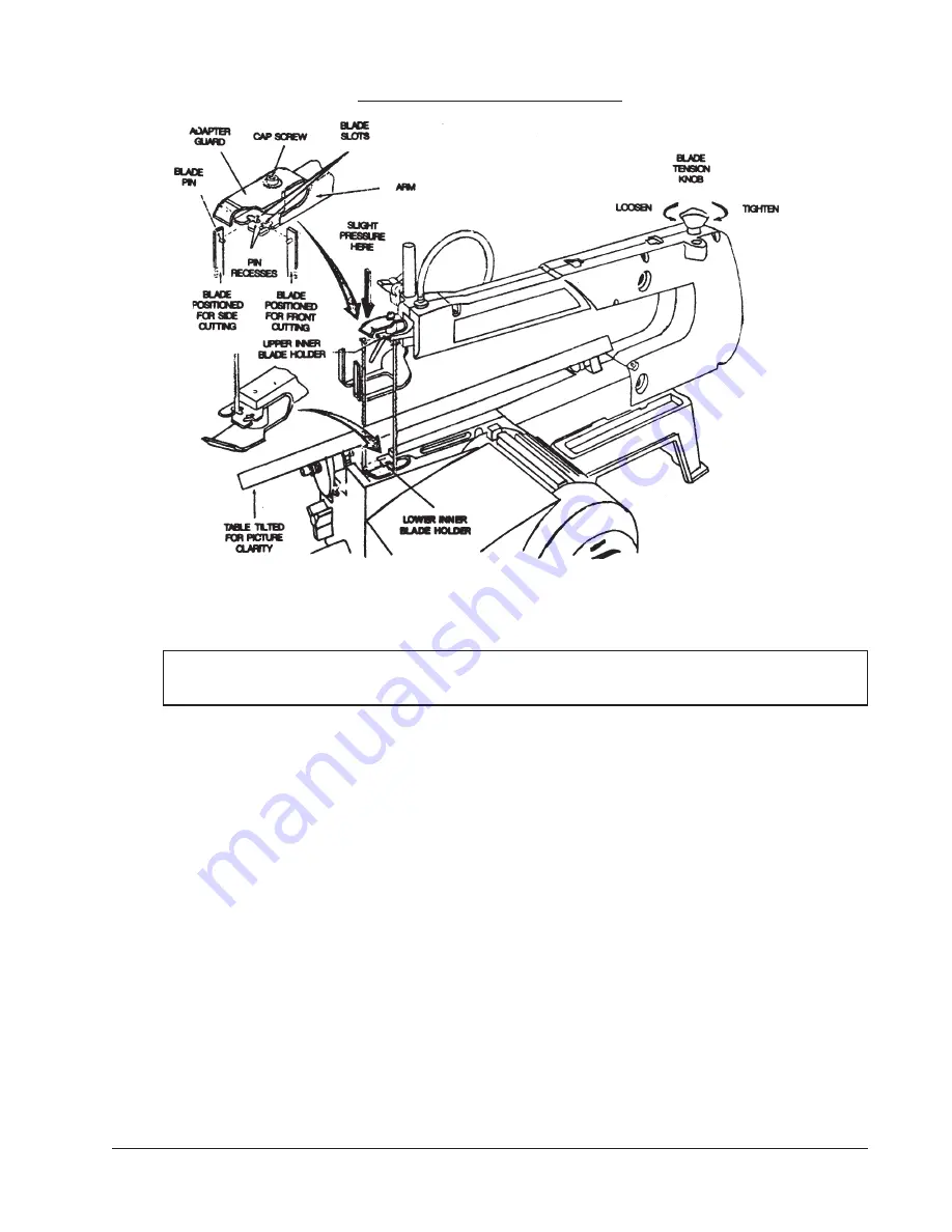
Look at the blade holders closely and notice the blade slots and recesses in the blade holders. The
blade holders are made so you can position the blade for cutting from the front or from the side of
the saw as shown in 

Figure 3

 above. Cutting from the side of the saw will be necessary if your

workpiece exceeds 16 inches in length. This allows your scroll saw to cut like a band saw. This
option is for 0

O

  table setting only.

4.

In order to cut, and to avoid uncontrollable lifting of the workpiece, the teeth of the blade used on
the scroll saw should always point downward.

5.

Install the blade by inserting one end of the blade through the access hole in the table and hook the
blade pin in the pin recess in the lower blade holder. Slide the top blade pin into the pin recess of the
inner upper blade holder. You may need to press down lightly on the upper blade holder to install
the blade.

6.

Carefully tighten the blade by rotating the blade tension knob clockwise until you feel the slack in the
 blade removed. Double check to see that pins are properly located in the blade holder. Then turn
the blade tension knob ONE full turn clockwise. This amount of blade tension should do well for
most cutting operations and blades.

Fig. 3. Installing the Blade

Brought to You by Augusta Flint

Summary of Contents for 41889

Page 1: ...Freight Tools All Rights Reserved No portion of this manual or any artwork contained herein may be reproduced in any manner shape or form without the express written consent of Harbor Freight Tools For technical questions and replacement parts please call 1 800 444 3353 www HarborFreight com Brought to You by Augusta Flint ...

Page 2: ...roved power cord 3 Easilyadjustabletableangle withscaleforaccuratemeasurement 4 Built in blower keeps blade clean and affords clear view of cutting operation 5 Uses readily available standard 5 pin blades SAVE THIS MANUAL Youwillneedthismanualforthesafetywarningsandcautions assemblyinstructions operatingprocedures maintenanceprocedures troubleshooting partslist anddiagram Keepyourinvoicewiththisma...

Page 3: ...e receptacle 10 DO NOT OVERREACH Keep proper footing and balance at all times Do not reach over or acrossrunningmachines 11 MAINTAINTOOLSWITH CARE Keep tools sharp and clean for better and safer performance Followinstructionsforlubricatingandchangingaccessories Inspectpowercordperiodicallyand if damaged haveitrepairedbyanauthorizedtechnician Inspectallmovingpartsandmountingbolts priortouse Control...

Page 4: ...xcessive kick out check your blade to assure that it is the proper type for the material being cut that it is installed with the teeth down and that it is sharp 11 Always wear ANSI certified eye protection and do not allow others nearby when using this tool Cuttingsandsplinterscanbeejectedathighspeedwhilecutting 12 Donothandlethebladeimmediatelyafteruse itmaybeveryhot potentiallycausingburns or in...

Page 5: ...scanbereadilymadewithascrollsaw 1 After selecting and installing the proper blade for the work at hand position the workpiece on the table 2 Lower the foot onto the workpiece so that it just rests on the surface of the material Tighten the footintopositionwiththeknob 3 With the material not touching the blade turn the power ON by pressing the upper part of the rocker switch 4 When the saw has come...

Page 6: ...onthesurface 5 DropFootLockKnob Loosenandtightenthisknobasyouadjustthedropfoot 6 BladeTensionKnob Allowsyoutoloosenortightenthebladetension Youalsousethisknobwhenreplacing theblade 7 TableLockKnob Thisknoballowsyoutoadjustthetableangleupto45degrees 8 DegreeScale Thisscaleindicatesthedegreefromhorizontalthatyouhavethetableset 9 PowerSwitch TurntheswitchuptoturnON anddowntoturnOFF 10 ElectricalBreak...

Page 7: ... of the saw as shown in Figure 3 above Cutting from the side of the saw will be necessary if your workpiece exceeds 16 inches in length This allows your scroll saw to cut like a band saw This option is for 0O table setting only 4 In order to cut and to avoid uncontrollable lifting of the workpiece the teeth of the blade used on the scroll saw should always point downward 5 Install the blade by ins...

Page 8: ...ided under the work table as a convenientreferenceforsettingtheapproximatetable angleforbevelcutting Whengreaterprecisionis required make practice cuts and adjust the table as necessaryforyourrequirements 3 NOTE When cutting at angles the drop foot can be tilted so it is parallel with the table surface and rests flush against the workpiece To tilt drop foot loosen the allen screw tilt the foot so ...

Page 9: ...rmAssembly 30 Hex Nut m5 31 Hex Head Bolt m5 x 30 32 SpacerBearing 33 SpacerBearing 34 LinkAssembly 35 AllenWrenches 2 5 3 4mm 36 Cord Clamp 37 Upper Holder 38 Hex Head Bolt m5 x 25 P N Description 39 FlatWasher 40 Lower Holder 41 ToothWasher 42 Hex Head Bolt m4 x 10 43 TableInsert 44 Knob 45 Blade 46 Pan Head Screw m4 x 16 47 BladeGuard 48 Tooth washer m5 49 Pan Head Screw m5 x 10 50 SwitchCover ...

Page 10: ...Page 10 SKU 41889 PARTS DIAGRAM 41889 SCROLLSAW Please see Parts List on Previous Page Brought to You by Augusta Flint ...

Reviews: