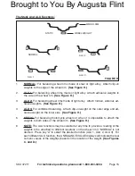
Page 10
SKU 47211
for technical questions, please call 1-800-444-3353.
gENERAL OpERATINg INsTRuCTIONs
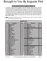
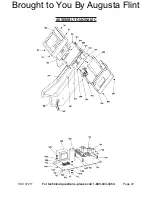
Note: For additional references to the parts listed below, refer to the Assembly diagrams
near the end of this manual.
To Mount A Wheel Onto The Balancer:
Connect the Plug (not provided) of the Power Cord (519) into a properly grounded,
3-hole, 220 volt, electrical receptacle.
(see Assy. diagram E.)
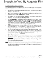
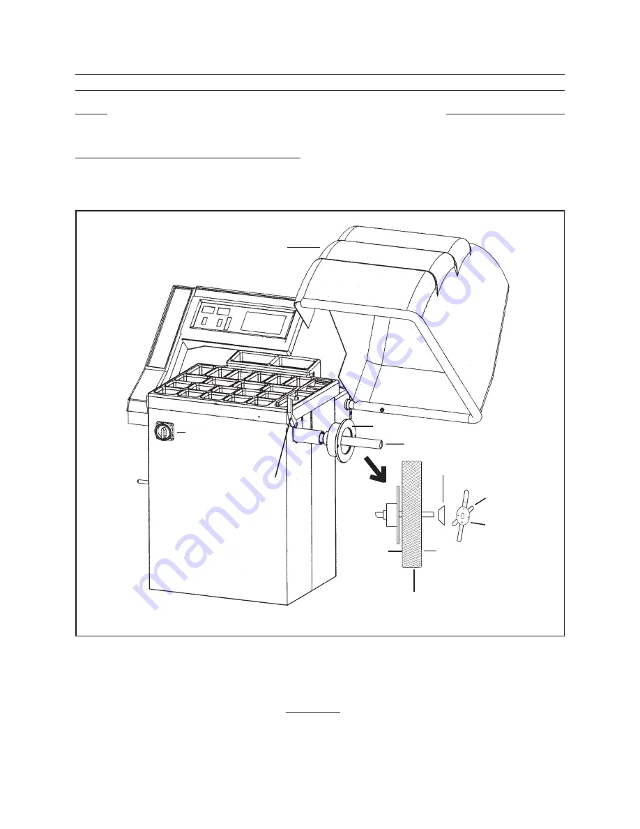
SAFETY GUARD
(504)
POWER SWITCH
(523)
RIM DISTANCE
POINTER
(202)
FLANGE (23)
TRANSMISSION SHAFT (24)
CONE (18)
THUMB LOCK
ADJUSTABLE
NUT
(16)
INNER
SIDE
OUTER
SIDE
WHEEL
fIguRE E
Raise the Safety Guard (504) to its full “UP” position.
(see figure E, and Assy. diagram E.)
Insert the center hole of the wheel rim (not provided) onto the Transmission Shaft
(24). Make sure to position the inner side of the wheel rim against the Flange (23).
(see figure E, and Assy. diagram A.)
1.
2.
3.
Brought to You By Augusta Flint


