Page 11
SKU 47211
for technical questions, please call 1-800-444-3353.
Select the proper size Cone diameter (18) that will ensure the wheel rim is tightly
secured (no wheel wobble) to the Transmission Shaft. Insert the Cone onto the
Transmission Shaft and partially through the center hole of the wheel rim.
(see figure E, and Assy. diagram A.)
Hold the Adjustable Nut (16) with both hands. While doing so, use your thumb to
move the Thumb Lock on the Adjustable Nut to the right. While holding the Thumb
Lock in position, slide the Adjustable Nut onto the Transmission Shaft (24) and firmly
against the Cone (18). Then, release the Thumb Lock and allow it to lock the wheel
rim in place on the Transmission Shaft.
(see figure E, and Assy. diagram A.)
To Make Wheel Measurements:
NOTE: Though the Wheel Balancer may be programmed to input numeric values
and display numeric values in ounces/inches or grams/mm, this manual will use
ounces/inches numeric values for ease of instruction. For instructions on how to
select and change numeric values in ounces/inches or grams/millimeters.
(see figure d.)
Remove all old weights, dirt, and debris from the wheel that is to be measured and
balanced.
Turn the Power Switch (523) to its “ON” position.
(see figure E, and Assy. diagram E.)
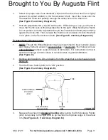
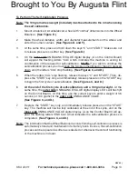
RIM DISTANCE
POINTER
(202)
TIRE
RIM DISTANCE
GAUGE (208)
WHEEL
RIM
fIguRE f
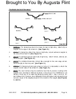
Measure the wheel rim
distance (reading a) by pulling the Rim Distance Pointer
(202) horizontally to the right until its tip touches the top/inner edge of the wheel
rim.
(see figures E, f, and Assy. diagram B.)
4.
5.
1.
2.
3.
4.
Brought to You By Augusta Flint


