Page 7
SKU 47211
for technical questions, please call 1-800-444-3353.
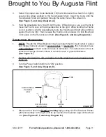
1/2” ANCHOR BOLT, WASHER, NUT
(NOT PROVIDED)
FRONT
VIEW
TOP
VIEW
1/2” MACHINE
MOUNTING HOLE
CONCRETE
FLOOR SURFACE
FLOOR
ANCHOR HOLE
fIguRE B
Secure the Wheel Balancer to the concrete floor surface, using three 1/2” diameter
concrete anchor bolts of appropriate length, three washers, and three nuts (not
provided).
(see figure B.)
To Attach The safety guard To The Wheel Balancer:
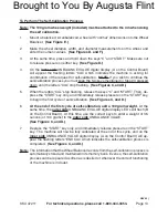
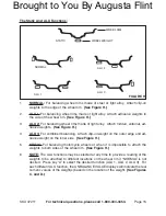
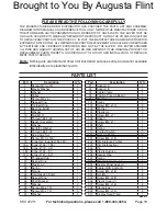
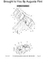
Slide the Sheath (106) onto the Shaft (108). Align the mounting hole of the Sheath
with the rear mounting hole of the Shaft. Then, secure the Sheath to the Shaft,
using the Screw (107).
(see Assy. diagram B.)
Slide the mounting hole of the Safety Guard (504) onto the Shaft (108). Make sure
to position the mounting hole of the Safety Guard against the pre-attached Sheath
(106).
(see Assy. diagram B.)
Slide the Plastic Lip (104) onto the exposed end of the Shaft (108). Align the mount-
ing hole of the Plastic Lip with the remaining mounting hole of the Shaft. Then,
secure the Plastic Lip to the Shaft, using the Screw (105). Attaching the Safety
Guard (504) to the machine is now completed.
(see Assy. diagram B.)
The Safety Guard (504) must always be in place while the Wheel Balancer is in
operation.
4.
1.
2.
3.
4.
Brought to You By Augusta Flint


