background image

Page 11

For technical questions, please call 1-888-866-5797.

Item 61790 
        

Sa

FE

ty

Op

E

ra

ti

O

n

Maint

E

nanc

E

S

E

tup

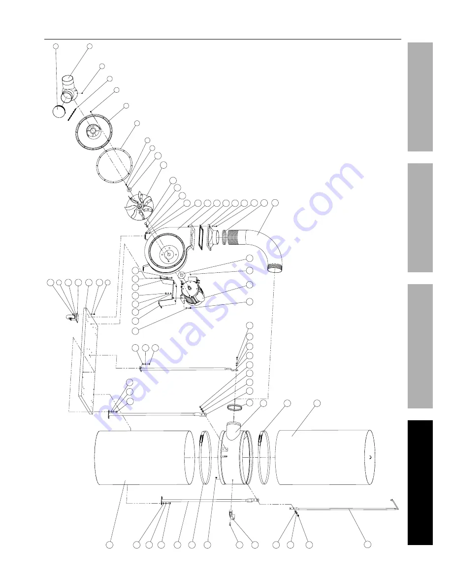
assembly Diagram

2

1

3

4

5

6

7

8

9

10

11

12

13

17

18

19

20

21

22

23

24

14

16

26

27

25

28

14

41

15

36

14

16

5

21

40

39

9

38

16

29

16

14

32

31

30

23

31

37

29

14

16

16

14

33

16

14

34

35

16

15

36

29

15

15

14

15

15

14

15

21

15

15

14

Summary of Contents for 61790

Page 1: ... and the receipt in a safe and dry place for future reference 18j When unpacking make sure that the product is intact and undamaged If any parts are missing or broken please call 1 888 866 5797 as soon as possible Copyright 2014 by Harbor Freight Tools All rights reserved No portion of this manual or any artwork contained herein may be reproduced in any shape or form without the express written co...

Page 2: ...en not in use and before servicing 2 Do not use outdoors or on wet surfaces 3 Do not allow to be used as a toy Close attention is necessary when used by or near children 4 Use only as described in this manual Use only manufacturer s recommended attachments 5 Do not use with damaged cord or plug If appliance is not working as it should has been dropped damaged left outdoors or dropped into water re...

Page 3: ...uilt into this product but must be supplied by the operator SaVE tHESE inStructiOnS Grounding instructions this appliance must be grounded if it should malfunction or breakdown grounding provides a path of least resistance for electric current to reduce the risk of electric shock this appliance is equipped with a cord having an equipment grounding conductor and grounding plug the plug must be inse...

Page 4: ... manual assembly 1 Place Caster 39 in place on the underside corner of the Base Plate 40 For all four corners of the Caster insert one Screw 5 through Washer 21 down into Base Plate and through Caster Thread on Nut 38 Repeat for remaining three Casters 2 Attach the first Collector Support 29 to the Base Plate Line up the Collector Support with holes on edge of the Base Plate Insert Bolt 16 down th...

Page 5: ...Figure E Filter Bag Support 33 collector Support 29 collector 30 Bolt 16 Figure E 8 Slide the Hose Clamp 23 onto the Hose 24 Slide Hose with Hose Clamp onto the Outlet Once the Hose is in place tighten the screw on the Hose Clamp until the Hose is securely fastened to the Outlet See Figure D 9 Slide the Hose Clamp onto the other end of the Hose Slide the top opening of the Hose over the duct in th...

Page 6: ...Page 6 For technical questions please call 1 888 866 5797 Item 61790 SaFEty OpEratiOn MaintEnancE SEtup Functions Hose Filter Bag collection Bag collector caster y inlet Fan Housing ...

Page 7: ...existing dust system or you can construct a new system 1 If constructing a new system connect 4 vent pipe not included to the 4 inlet side of the collector 2 Determine the size of the dust ports on your tools and run vacuum hoses from each tool to an appropriate sized adapter and into the 4 vent pipe none included table a rEcOMMEnDED MiniMuM WirE GauGE FOr EXtEnSiOn cOrDS 120 VOLt naMEpLatE aMpErE...

Page 8: ... any other condition that may affect its safe operation 2 aFtEr uSE wipe external surfaces of the appliance with clean cloth Store in an indoor dry area out of reach of children 3 All parts are permanently lubricated Do not use additional lubrication 4 Check Collection and Filter Bags 1 each prior to each use for tears or fraying Replace if necessary 5 Periodically tighten the Filter Clamps 31 and...

Page 9: ...ord If an extension cord is needed use one with the proper diameter for its length and load See table a on page 7 Overheating 1 Blocked motor housing vents 2 Motor being strained by long or small diameter extension cord 3 Motor being strained by over full Collection Bag 1 Wear ANSI approved safety goggles and NIOSH approved dust mask respirator while blowing dust out of motor using compressed air ...

Page 10: ...rts List and Diagram pLEaSE rEaD tHE FOLLOWinG carEFuLLy THE MANUFACTURER AND OR DISTRIBUTOR HAS PROVIDED THE PARTS LIST AND ASSEMBLY DIAGRAM IN THIS MANUAL AS A REFERENCE TOOL ONLY NEITHER THE MANUFACTURER OR DISTRIBUTOR MAKES ANY REPRESENTATION OR WARRANTY OF ANY KIND TO THE BUYER THAT HE OR SHE IS QUALIFIED TO MAKE ANY REPAIRS TO THE PRODUCT OR THAT HE OR SHE IS QUALIFIED TO REPLACE ANY PARTS O...

Page 11: ...1790 SaFEty OpEratiOn MaintEnancE SEtup assembly Diagram 2 1 3 4 5 6 7 8 9 10 11 12 13 17 18 19 20 21 22 23 24 14 16 26 27 25 28 14 41 15 36 14 16 5 21 40 39 9 38 16 29 16 14 32 31 30 23 31 37 29 14 16 16 14 33 16 14 34 35 16 15 36 29 15 15 14 15 15 14 15 21 15 15 14 ...

Page 12: ...so the above limitation of exclusion may not apply to you THIS WARRANTY IS EXPRESSLY IN LIEU OF ALL OTHER WARRANTIES EXPRESS OR IMPLIED INCLUDING THE WARRANTIES OF MERCHANTABILITY AND FITNESS To take advantage of this warranty the product or part must be returned to us with transportation charges prepaid Proof of purchase date and an explanation of the complaint must accompany the merchandise If o...

Reviews: