Page 4
For technical questions, please call 1-888-866-5797.
Item 61790
Sa
FE
ty
Op
E
ra
ti
O
n
Maint
E
nanc
E
S
E
tup
Specifications
Electrical Rating
120VAC / 60Hz / 15A / 2HP
Single Phase
RPM
3450
Bag Dimensions
Top=19-1/2" Dia. x 30"L
Bottom=19-1/2" Dia. x 30-7/8"L
Bag Filtration Ratio
5 Microns
Intake
4-3/8" ID (screen & filter)
Exhaust Diameter
4-1/2 Inch ID With Screen
Setup - Before use:
read the EntirE iMpOrtant SaFEty inFOrMatiOn section at the beginning of this
manual including all text under subheadings therein before set up or use of this product.
tO prEVEnt SEriOuS inJury FrOM acciDEntaL OpEratiOn:
turn the power Switch of the appliance off and unplug the appliance from its
electrical outlet before performing any procedure in this section.
note:
For additional information regarding the parts listed in the following pages,
refer to the Assembly Diagram near the end of this manual.
assembly
1. Place Caster (39) in place on the underside corner
of the Base Plate (40). For all four corners of the
Caster insert one Screw (5) through Washer (21)
down into Base Plate and through Caster. Thread
on Nut (38). Repeat for remaining three Casters.
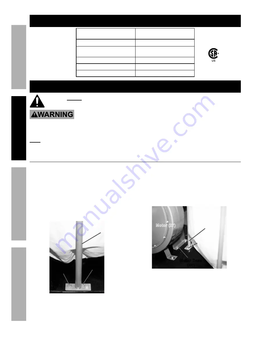
2. Attach the first Collector Support (29) to the
Base Plate. Line up the Collector Support with
holes on edge of the Base Plate. Insert Bolt (16)
down through Washers (15,14), Base Plate and
secure in place with Nut (2). (See Figure A.)
collector
Support (29)
Base
plate (40)
Bolt (16)
Figure a
3. Repeat for second Collector Support on
the opposite edge of the Base Plate.
4. Attach the third Collector Support through
the inside holes near where the Motor
Base (41) will be mounted. (See Figure B)
Insert Bolt down through Washers and Base
Plate and secure in place with Nut.
collector
Support (29)
Bolt (16)
Motor (27)
Motor Base
(41)
Figure B
5. The Fan Housing (17) is attached to the Motor (27)
and Motor Base as a single unit. Secure the Motor
Base to the Base Plate (40) using six Bolts, twelve
Washers and six Nuts. (See Figure B and Figure C.)
227541


