background image

EXTENSION CORDS

1.

Grounded tools require a three wire extension cord.  Double Insulated  tools
can use either a two or three wire extension cord.

2.

As the distance from the supply outlet increases, you must use a heavier gauge
extension cord.  Using extension cords with inadequately sized wire causes a
serious drop in voltage, resulting in loss of power and possible tool damage.
(See Figure C, next page.)

3.

The smaller the gauge number of the wire, the greater the capacity of the cord.
For example, a 14 gauge cord can carry a higher current than a 16 gauge cord.
(See Figure C.)

4.

When using more than one extension cord to make up the total length, make
sure each cord contains at least the minimum wire size required.
(See Figure C.)

5.

If you are using one extension cord for more than one tool, add the nameplate
amperes and use the sum to determine the required minimum cord size.
(See Figure C.)

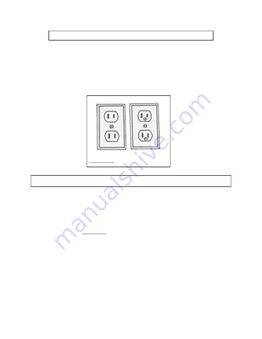
FIGURE B

DOUBLE  INSULATED TOOLS: TOOLS WITH TWO  PRONG  PLUGS

4.

Tools marked “Double Insulated” do not require grounding.  They have a special
double insulation system which satisfies OSHA requirements and complies with
the applicable standards of Underwriters Laboratories, Inc., the Canadian
Standard Association, and the National Electrical Code.  (See Figure B.)

5.

Double insulated tools may be used in either of the 120 volt outlets shown in the
following illustration.  (See Figure B.)

SKU 93815

PAGE 8

Summary of Contents for 93815

Page 1: ...Copyright 2006 by Harbor Freight Tools All rights reserved No portion of this manual or any artwork contained herein may be reproduced in any shape or form without the express written consent of Harbo...

Page 2: ...invoice number on the inside of the front cover Keep this manual and invoice in a safe and dry place for future reference GENERAL SAFETY RULES WARNING SAVE THESE INSTRUCTIONS WORK AREA 1 Keep your wo...

Page 3: ...such as pipes radiators ranges and refrigerators There is an increased risk of electric shock if your body is grounded 7 Do not expose splitter to rain or wet conditions Water entering the splitter w...

Page 4: ...lication The correct splitter will do the job better and safer at the rate for which it is designed 18 Do not use the power tool if the Power Switch does not turn it on or off Any tool that cannot be...

Page 5: ...hazard Electrical Safety Never operate this tool if there is an electrical hazard Never operate an electrical tool in wet conditions Never operate this tool with an improper electrical cord or extensi...

Page 6: ...is plugged into an electrical outlet Turn off the splitter and unplug it from its electrical outlet before leaving 9 Always unplug the splitter from its electrical outlet before performing and inspect...

Page 7: ...to an electrically live terminal See Figure A 3 Your tool must be plugged into an appropriate outlet properly installed and grounded in accordance with all codes and ordinances The plug and outlet sho...

Page 8: ...than one extension cord to make up the total length make sure each cord contains at least the minimum wire size required See Figure C 5 If you are using one extension cord for more than one tool add...

Page 9: ...damp or wet areas RECOMMENDED MINIMUM WIRE GAUGE FOR EXTENSION CORDS 120 VOLT NAMEPLATE AMPERES At Full Load EXTENSION CORD LENGTH 25 Feet 50 Feet 75 Feet 100 Feet 150 Feet 0 2 0 18 18 18 18 16 2 1 3...

Page 10: ...lows Screw Handle A D Below into Handle B E Below The Log Splitter is ready for use after reading and adhering to all Saftety Warnings and Cautions and Operation and Maintenance instructions provided...

Page 11: ...c oil see Checking Changing Hydraulic Oil section on page 12 5 Position Splitter Securely Be sure the Splitter is positioned firmly on level solid ground If necessary block the Wheels 25 with wedges t...

Page 12: ...ce Unplug the Tool from the Power Source CHECKING CHANGING THE HYDRAULIC OIL Please refer to Figure E on this page and Parts Diagram on page 15 1 Make sure the LOG PUSHER 49A is fully retracted 2 Care...

Page 13: ...rocess using progressively larger wedges until the jammed log is freed Warning Never hammer on the jammed log or place your hands near the log when attempting to free it SKU 93815 PAGE 13 THE MANUFACT...

Page 14: ...PARTS LIST SKU 93815 PAGE 14...

Page 15: ...ASSEMBLY DIAGRAM SKU 93815 PAGE 15 NOTE Some parts are listed and shown for illustration purposes only and are not available individually as replacement parts...

Page 16: ...FITNESS To take advantage of this warranty the product or part must be returned to us with transportation charges prepaid Proof of purchase date and an explanation of the complaint must accompany the...

Reviews: