Page 5 SKU # 95647
5.
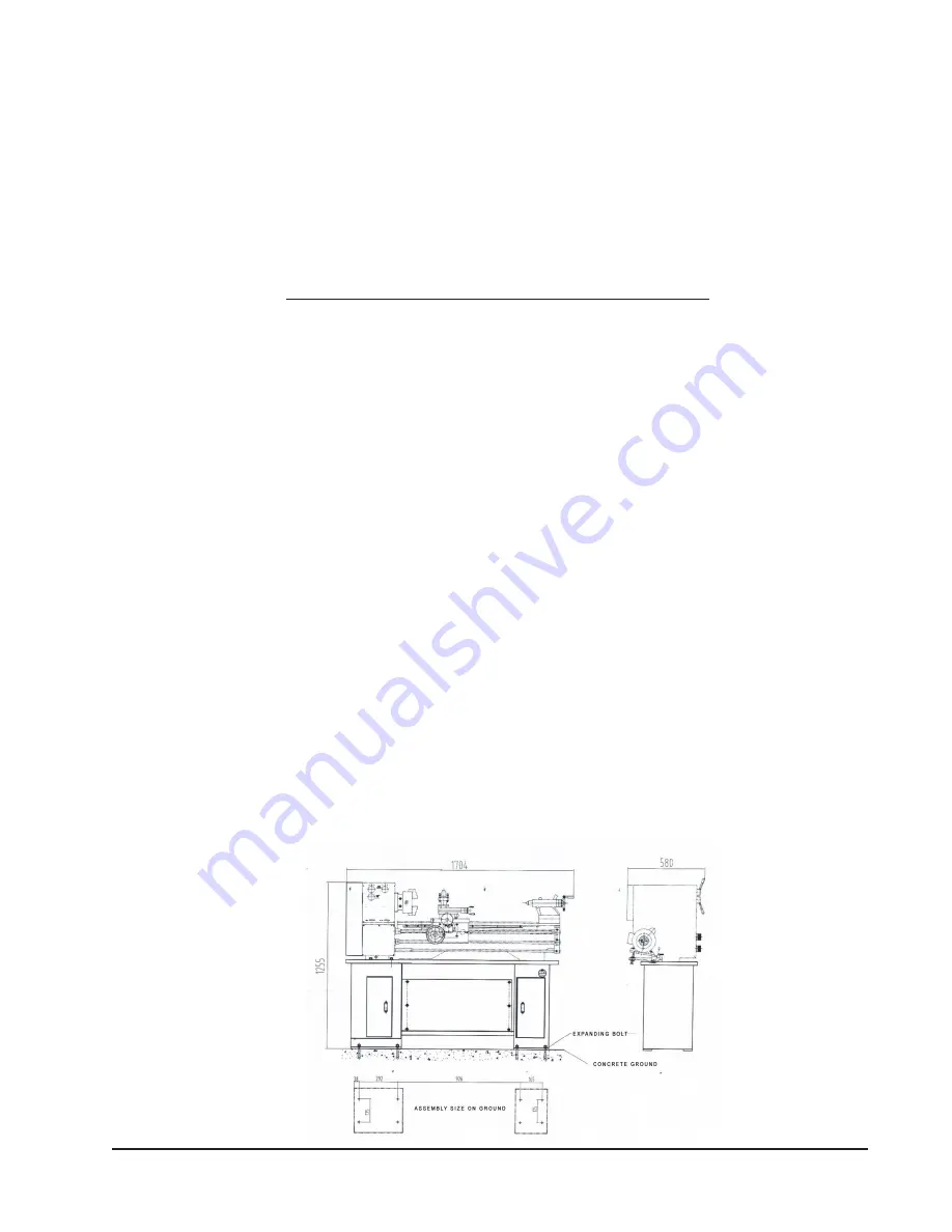
Once the Stands are positioned properly on a solid level floor, place the Lathe’s oil pan on them.
Align the mounting holes in the oil pan with the holes in the Stands. If needed, place shims (not in
cluded between the oil/chip tray and the Lathe Stands. Check the level and position of the Stands
again to be sure that when the Lathe is positioned on the stands and chip tray it will be level, solid and
aligned with the mounting holes in the Stands and tray.
HOISTING AND LEVELING LATHE ONTO STAND
WARNING: DO NOT ATTEMPT TO LIFT THE LATHE BY YOURSELF.
The 43681 Lathe weighs over 800 Lbs., and cannot be lifted safely by one or several strong men.
Be sure the Lathe is balanced on the hoist or lift you will use to move it before moving the Lathe.
1.
Before hoisting, lifting or moving the Lathe, move the tailstock and apron to the far right
end of the bedway (away from the headstock) and lock them in place there. This will help to
balance the overall mass of the machine near the center.
2.
Use pads (not included) to protect the machine from damage by the equipment used to hoist it.
3.
Use a hydraulic lift, fork lift, or hoist to position the Lathe onto the Stand. Read and adhere to all
safety warnings and instructions provided by the manufacturer of the lifting device that is being used.
4.
When the lathe is positioned on the oil tray and Stand, align the mounting holes and drop in the
mounting bolts.
5.
Check the level of the machine. Using a spirit level, check to be sure that the bed of the lathe
is level both horizontally and front to back. If there is any out of level, correct it now.
Depending on your installation, use angled iron levelers (shims) to adjust the machine into exact
level front to back and side to side. Check both ends of the tool before being satisfied.
Be sure the machine is level, positioned solidly, and is resistant to vibration.
6.
Fasten the lathe to the Stand and the Lathe’s oil tray by inserting a bolt through a lock washer from the
inside of the Stand and upward through the oil tray and lathe. Fasten with a washer and nut.
Repeat this for each of the four mounting holes in the headstock, and both mounting holes in
the tailstock. Tighten securely. Recheck and readjust level if required.
NOTE: Periodically recheck the lev
el of the machine to assure that it remains level while it is in use.


