background image

Page 11

SKU 65345

For technical questions, please call 1-800-444-3353.

smaller than this can pass through 

the Spindle to work on longer pieces.

Swing:  

A dimension representing 

the largest diameter workpiece that a 

lathe can rotate. The 10” x 18” Lathe 

means the maximum size workpiece 

that can rotate without hitting the Bed 

is 10” in diameter.

Tailstock:  

Assembly that slides 

along the ways and can be locked in 

place. Used to hold long workpieces 

in place or to mount a drill chuck.

Tailstock Handwheel:  

Moves the 

Tailstock in and out.

Tool rest:  

A device mounted on the 

compound that holds the cutting tool.

Turning:  

A lathe operation that re-

moves wood from the outside diam-

eter of the workpiece.

Ways:  

Surface along the top of the 

Bed on which the Tailstock rides. The 

ways are aligned with the centerline 

of the lathe.

ADJuSTMENTS

To Adjust The Spindle Speed (rpM):

To prevent serious injury, make sure the 

Lathe’s Power Switch (46) is in its 

“OFF”


position and the machine is unplugged 

from its electrical 

outlet.

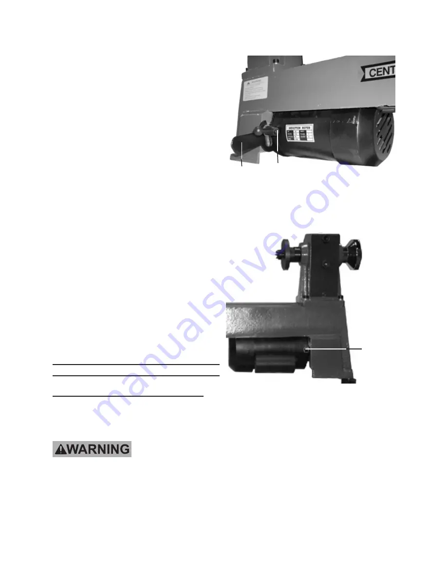
Loosen the Belt Tension Screw (33).  

1. 

Then move the Belt Tension Lever 

(31) to release tension from the Drive 

Belt (26). 

 (See Figure c.)

FIgurE c

BELT

TENSION

ScrEW

(33)

BELT

TENSION

LEVEr

(31)

2.  Loosen the Motor Mount Screw (27).  

(See Figure D.)

FIgurE D

MOTOr

MOuNT

ScrEW

(27)

3.  Open the Back Lid (20) and Side Lid 

(63). 

(See Figures E and F, next page.)

rEV 09e

Summary of Contents for CENTRAL MACHINERY 65345

Page 1: ...n serious injury Save this manual Copyright 2008 by Harbor Freight Tools All rights reserved No portion of this manual or any artwork contained herein may be reproduced in any shape or form without th...

Page 2: ...SION CORDS 7 SYMBOLOGY 8 SPECIFICATIONS 8 UNPACKING 9 PRODUCT FEATURES 9 ASSEMBLY INSTRUCTIONS 9 WORK AREA SET UP 9 DEFINITION OF TERMS 10 ADJUSTMENTS 11 OPERATING INSTRUCTIONS 15 MAINTENANCE AND SERV...

Page 3: ...t symbol indicates a hazardous situation which if not avoided could result in minor or moderate injury NOTICE is used to address practices not related to personal injury CAUTION without the safety ale...

Page 4: ...non skid safety shoes hard hat or hearing protection used for appropriate conditions will reduce personal injuries Remove any adjusting key or c wrench before turning the power tool on A wrench or a k...

Page 5: ...e the lowest speed when starting a 5 new workpiece Always stop the Lathe at its slow 6 est speed If the Lathe is run so fast that it vibrates there is a risk that the workpiece will be thrown or the c...

Page 6: ...ctrical shock Any power cord must be properly grounded Ground Fault Circuit Inter rupter GFCI should also be imple mented it prevents sustained elec trical shock Some dust created by power sand 23 ing...

Page 7: ...prong in the plug is 2 connected through the green wire in side the cord to the grounding system in the tool The green wire in the cord must be the only wire connected to the tool s grounding system a...

Page 8: ...0 150 0 2 0 18 18 18 18 16 2 1 3 4 18 18 18 16 14 3 5 5 0 18 18 16 14 12 5 1 7 0 18 16 14 12 12 7 1 12 0 18 14 12 10 12 1 16 0 14 12 10 16 1 20 0 12 10 TABLE A Based on limiting the line voltage drop...

Page 9: ...ein before set up or use of this product To prevent serious injury from accidental operation Turn the Power Switch 46 of the Lathe to its OFF position and unplug the tool from its electrical outlet be...

Page 10: ...pered cylinder with a pointed tip and a Morse Taper shaft Used in the tailstock to support the end of long workpieces May also be used in the Headstock spindle to support work between centers at both...

Page 11: ...ound that holds the cutting tool Turning A lathe operation that re moves wood from the outside diam eter of the workpiece Ways Surface along the top of the Bed on which the Tailstock rides The ways ar...

Page 12: ...per grooves on the Drive Pul ley 25 and Motor Pulley 29 See Figure G FIGURE G 750 1100 1600 2200 3200 5 Move the Belt Tension Lever 31 down adjusting tension so that 1 2 of Drive Belt 26 deflection is...

Page 13: ...in small increments as needed to achieve the proper clamping pressure See Figure J and Assy Diagram FIGURE J RELEASE LEVER 7 TAILSTOCK 5 To Adjust The Tool Rest Loosen the Lock Handle 40 and slide 1...

Page 14: ...4 5 counterclockwise until the Tail Axis 8 bottoms out causing the Cup Center 11 to be forced out of the Tail Axis See Figure M The Lock Lever 6 must always be locked down while the Lathe is in use Th...

Page 15: ...igure O OPERATING INSTRUCTIONS With the Power Switch 46 in its 1 OFF position and the Lathe un plugged from its electrical outlet make all necessary adjustments to the machine as previously discussed...

Page 16: ...Tool Rest 35 approxi 10 mately 1 4 away from the workpiece and approximately 1 8 above the center line See Figure R Make sure to test the set up by hand 11 turning the workpiece to ensure there is en...

Page 17: ...gure U Mark the center of the backing block 18 See Figure U Drill a 14 diameter hole through the 19 center of the backing block See Figure U Glue the center of the backing block 20 to the center of th...

Page 18: ...h ISO 68 or SAE 20W oil Lubricate the Tailstock oiling point 4 every five uses or once per week if used frequently 5 WARNING If the Power Cord 45 of this Lathe is damaged it must be replaced only by a...

Page 19: ...rkpieces or bowls Headstock and or tailstock 1 improperly located at ends of workpiece Workpiece is unbalanced 2 Check for proper workpiece 1 centers Cut off stock until workpiece is 2 balanced Lathe...

Page 20: ...Lock Handle Tool Rest Base 1 12 Headstock Spur Center 1 41 Lock Lever 1 13 Faceplate 1 42 Bolt 1 14 Headstock Spindle 1 43 Lock Plate 1 15 Ball Bearing 2 44 Hex Nut 1 16 Retaining Ring 1 45 Power Cord...

Page 21: ...Page 21 SKU 65345 For technical questions please call 1 800 444 3353 ASSEMBLY DIAGRAM...

Page 22: ...r consequential damages arising from the use of our product Some states do not allow the exclusion or limitation of incidental or consequential damages so the above limitation of exclusion may not app...

Reviews: