background image

SKU 95668        

 For technical questions, please call 1-800-444-3353 

PAGE 3

ELEcTRIcAL SAFETY

1. 

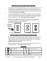
grounded tools must be plugged into an outlet properly installed and 

grounded in accordance with all codes and ordinances.  Never remove the   

grounding prong or modify the plug in any way.  Do not use any adapter  

plugs. Check with a qualified electrician if you are in doubt as to whether    

the outlet is  properly grounded.

  If the tools should electrically malfunction or    

break down, grounding provides a low resistance path to carry electricity away    

from the user.

2. 

Avoid body contact with grounded surfaces such as pipes, radiators, 

ranges, and refrigerators.  

There is an increased risk of electric shock if your 

body is grounded.

3. 

Do not expose power tools to rain or wet conditions.  

Water entering power    

equipment will increase the risk of electric shock.

4. 

Do not abuse the Power cord.


Never use the Power cord to pull the Plug    

from an outlet.  Keep the Power cord away from heat, oil, sharp edges, or    

moving parts.  Replace damaged Power cords immediately.

  Damaged 


Power Cords increase the risk of electric shock.

PERSONAL SAFETY


1. 

Stay alert.  Watch what you are doing, and use common sense when   


operating the Wood Shaper.  Do not use the tool while tired or under the    

influence of drugs, alcohol, or medication.

  A moment of inattention while  


operating power tools may result in serious personal injury.

2. 

Dress properly.  Do not wear loose clothing or jewelry.  contain long hair.     

Keep your hair, clothing, and gloves away from moving parts.

  Loose   


clothes, jewelry, or long hair can be caught in moving parts.

3. 

Use the right product for the job.  

Do not attempt to force small equipment to    

do the work of larger industrial equipment.  There are certain applications for  


which this product was designed.  It will do the job better and safer at the rate    

and capacity for which it was designed.  Do not modify this product, and do not    

use this product for a purpose for which it was not designed.


area from debris such as chips and sparks.  Provide barriers or shields as   


needed.  Children and visitors should never be in the work area.
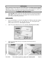
4. 

Avoid accidental starting.


Be sure the Power Switch is off before plugging

Summary of Contents for CENTRAL MACHINERY 95668

Page 1: ...reserved No portion of this manual or any artwork contained herein may be reproduced in any shape or form without the express written consent of Harbor Freight Tools Diagrams within this manual may no...

Page 2: ...ildren and visitors away while operating power equipment Distractions can cause you to lose control Protect others in the work WARNING READ AND UNDERSTAND ALL INSTRUCTIONS Failure to follow all instru...

Page 3: ...moving parts Replace damaged Power Cords immediately Damaged Power Cords increase the risk of electric shock PERSONAL SAFETY 1 Stay alert Watch what you are doing and use common sense when operating t...

Page 4: ...be controlled with the Power Switch is dangerous and must be replaced 3 Disconnect the Power Cord Plug from the power source before making any adjustments changing accessories or storing the Wood Shap...

Page 5: ...sonnel could result in a risk of injury 2 When servicing a tool use only identical replacement parts Follow instructions in the Inspection Maintenance And Cleaning section of this manual Use of unauth...

Page 6: ...ot included as a safety device In other situations using a push stick can be dangerous If the push stick comes in contact with the Cutter on the end grain it can be violently propelled from your hand...

Page 7: ...h approved safety equipment such as those dust masks that are specially designed to filter out microscopic particles California Health Safety Code 25249 5 et seq 28 WARNING People with pacemakers shou...

Page 8: ...e 3 Prong Plug and Outlet The tool must be plugged into an appropriate outlet properly installed and 3 grounded in accordance with all codes and ordinances The plug and outlet should look like those i...

Page 9: ...its OFF position and the unit is unplugged from its electrical outlet prior to performing any assembly procedures Stand Assembly 2 Lay one Side Panel 1 on the floor and attach the Tie Bars 2 with the...

Page 10: ...SSEMBLY WORK TABLE 52 Optional Table Spacer Installation Your shaper comes with a Table Spacer Installation Kit that will enable you 1 to make shallow cuts and utilize the upper blade area of most rou...

Page 11: ...2 HOUSING BRACKET 87 PHILIPS HEAD SCREWS 78 HEX NUTS 84 Installing The Spindle Prior to installation make sure to remove any oil grease dirt and debris from 1 the Spindle 105 Draw Bar 121 and Spindle...

Page 12: ...tapered Draw Bar Hex Nut 122 onto the end of the Draw Bar 121 under the Work Table 52 making sure the tapered side of the Hex Nut is facing upward See Figure L 5 Place a wrench not included on the top...

Page 13: ...ate freely on center 7 WARNING When using a Router Bit 103 104 operate the Wood Shaper only in a counterclockwise direction Router Bits are designed to cut in the counterclockwise direction only DO NO...

Page 14: ...are parallel with each other use a straight edge that is long enough to span the entire length of the two Fences 60 See Figure Q 3 Adjust the position of the Fence 60 by turning the Knob 64 See Figure...

Page 15: ...ure the Table Insert 53 53A is seated and flush with the Work Table 52 surface See Figure R TABLE INSERT 53 53A WORK TABLE 52 FIGURE R Belt Adjustment 1 The Wood Shaper uses a Belt 123 on two Pulleys...

Page 16: ...and Cutter rotate counterclockwise See Figure T 3 When the Forward Reverse Switch 144 is pointing to the REV position the Spindle 105 and Cutter rotate clockwise See Figure T 4 Always try to operate...

Page 17: ...provided Arbor Wrench 146 See Figures W and X 4 Check to make sure the Cutter not included will rotate in the correct direction SAFETY WASHER 97 UPPER SPINDLE NUT 96 FIGURE W ARBOR WRENCH 146 UPPER SP...

Page 18: ...gular shapes Rub Collars 98 99 100 are a necessity Some examples of when you would use a Rub Collar are raising arched or tombstone door panels round table tops or any other cut that needs to have its...

Page 19: ...ng the workpiece into the Cutter See Figure BB BETWEEN RUB COLLAR 98 99 100 CUTTER CUTTER FIGURE BB C Below the Cutter This set up allows the cut to be viewed by the operator However it is also the mo...

Page 20: ...oises The Wood Shaper should run smoothly with little or no vibrations WARNING If there is an unusual noise or vibration shut off the machine immediately DO NOT use the Wood Shaper any further until t...

Page 21: ...e Wood Shaper 9 Using a piece of scrap wood advance the workpiece 8 into the Cutter and turn off the machine DO NOT remove the workpiece from the infeed Fence 60 See Figure DD 10 Once the Cutter has c...

Page 22: ...Aluminum Fence 60 See Figure FF 6 Place a straight edge against the infeed and outfeed Aluminum Fences 60 to check alignment Once they are both in alignment make sure the Lock Handle 61 is tightened...

Page 23: ...le on the Work Table 52 so you can feed the workpiece into and against the rotation of the Cutter See Figures HH 5 Install the Cutter so it will cut in the correct direction Then adjust the Spindle 10...

Page 24: ...uch as toggle clamps not included to hold the workpiece or you can use custom guards for safety and protection See Figure KK CAUTION Make sure to design jigs and fixtures so screws and clamps DO NOT c...

Page 25: ...solvents Do not introduce liquids to any electrical part of the unit 4 To store keep the machine in a clean dry safe location out of reach of children and other unauthorized people 5 CAUTION All maint...

Page 26: ...r the Cutter chatters 1 The Stand of the Wood Shaper is unstable and wobbles 2 The Spindle or Cutter is loose or out of alignment 3 The Wood Shaper has a loose Motor or Spindle Cartridge 1 Stabilize t...

Page 27: ...t M4 0 7 27 Hex Bolt M8 1 25 x 12 85 Ring Guard 28 Table Leg 86 Hex Bolt M8 1 25 x 30 87 Housing Bracket 30 Hex Bolt M8 1 25 x 25 88 Clamp Sleeve Left 31 Hex Bolt M12 1 75 x 30 89 Stuff Ring 32 Lock W...

Page 28: ...otor Mount Plate 122 Draw Bar Hex Nut M8 1 0 137 Flat Washer 3 8 123 Belt 690 x 10mm 138 Hex Nut M8 1 25 124 Hex Bolt M8 1 25 x 12 139 Lock Washer 12mm 125 Flat Washer 3 8 140 Lock Washer 8mm 126 Belt...

Page 29: ...5668 For technical questions please call 1 800 444 3353 PAGE 29 ASSEMBLY DIAGRAM NOTE Some parts are listed and shown for illustration purposes only and are not available individually as replacement p...

Page 30: ...for incidental contingent special or consequential damages arising from the use of our product Some states do not allow the exclusion or limitation of incidental or consequential damages so the above...

Reviews: