

SKU 95668
For technical questions, please call 1-800-444-3353
PAGE 8
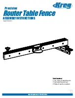
THIS PRODUcT
USES A
3-PRONg PLUg
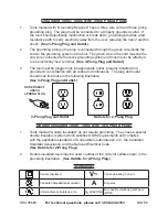
grounded Tools: Tools with Three Prong Plugs
Tools marked with “Grounding Required” have a three wire cord and three prong
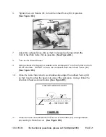
1.
grounding plug. The plug must be connected to a properly grounded outlet. If
the tool should electrically malfunction or break down, grounding provides a low
resistance path to carry electricity away from the user, reducing the risk of electric
shock.
(See 3-Prong Plug and Outlet.)
The grounding prong in the plug is connected through the green wire inside the
2.
cord to the grounding system in the tool. The green wire in the cord must be the
only wire connected to the tool’s grounding system and must never be attached
to an electrically “live” terminal.
(See 3-Prong Plug and Outlet.)
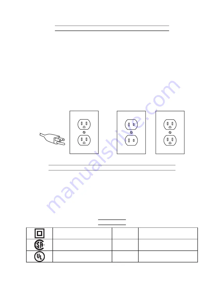
The tool must be plugged into an appropriate outlet, properly installed and
3.
grounded in accordance with all codes and ordinances. The plug and outlet
should look like those in the following illustration.
(See 3-Prong Plug and Outlet.)
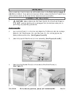
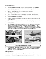
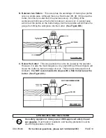
3-Prong Plug and Outlet
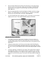
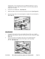
Outlets for 2-Prong Plug
Double Insulated Tools: Tools with Two Prong Plugs
Tools marked “Double Insulated” do not require grounding. They have a special
1.
double insulation system which satisfies OSHA requirements and complies
with the applicable standards of Underwriters Laboratories, Inc., the Canadian
Standard Association, and the National Electrical Code.
(See Outlets for 2-Prong Plug.)
Double insulated tools may be used in either of the 120 volt outlets shown in the
2.
preceding illustration.
(See Outlets for 2-Prong Plug.)
Symbology
Double Insulated
V~
Volts Alternating Current
Canadian Standards Association
A
Amperes
Underwriters Laboratories, Inc.
n0 xxxx/min.
No Load Revolutions per Minute
(RPM)