background image

Page 5

SKU 90288

For technical questions, please call 1-800-444-3353.

Air Connection

AIR SANDER

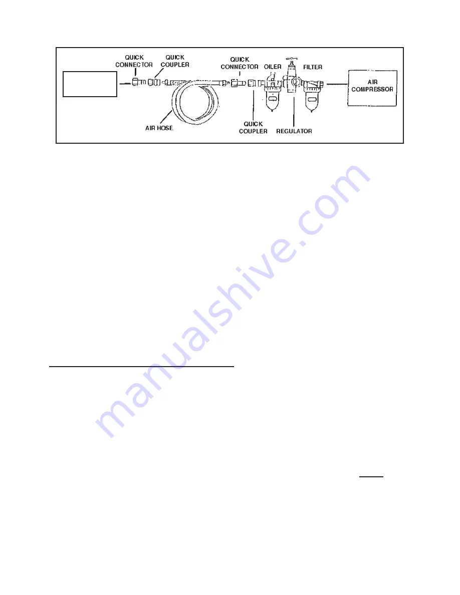
Note: Air Compressor is not supplied.  You will need an Air Compressor with a 

minimum rating of one horsepower, 4 CFM delivery at 90 PSI, and a 12 Gallon Air 

Tank.  Refer to the above illustration for complete air connection setup.
You may use Quick Connectors, Quick Couplers, (not supplied) and Air Regulator 

as shown in the Diagram above. Do not connect Couplers directly to the Air Inlet 

(2). Doing so will increase the overall bulk of the tool and strain the Inlet Threads.
Be sure to follow all safety precautions as listed on Pages 2-4 of this manual and 

the instruction manual for the Air Compressor being used.
This air tool requires lubrication during operation. For best results, it is recom-

mended to have an oiler and water filter in line with the air supply as shown in the 

diagram above. This will extend the life of the tool.

To Attach Sanding Paper And The Pad:

1. 

Ensure that the Pad is 

firmly

 screwed onto the Drive Spindle (38).  The 

Spindle Lock (41) turns to engage the Drive Spindle (38), allowing the 

Pad (44) to be threaded on securely.  Turn the Spindle Lock (41) back out 

of the way before use.

  If the Orbital Hub is still in the locked position 

during use, then the Sander will not operate properly.  (See Bottom 

View, next page.)

2. 

The Sander 

only

 uses 

6” diameter, PSA Stick,

 (self-sticking) Sanding 

Paper (not included).  Make sure to attach the Sanding Paper firmly to 

the Pad (44).

REV 05e

Summary of Contents for 90288

Page 1: ... rights reserved No portion of this manual or any artwork contained herein may be reproduced in any shape or form without the express written consent of Harbor Freight Tools Diagrams within this manual may not be drawn proportionally Due to continuing improvements actual product may differ slightly from the product described herein Tools required for assembly and service may not be included For te...

Page 2: ...all instructions before using this tool 1 Keep work area clean Cluttered areas invite injuries 2 Observe work area conditions Do not use machines or power tools in damp or wet locations Don t expose to rain Keep work area well lighted Do not use electrically powered tools in the presence of flammable gases or liquids 3 Keep children away Children must never be allowed in the work area Do not let t...

Page 3: ...rting Be sure the air compressor switch is in the Off position when not in use and before connecting to this tool Do not carry any tool with your finger on the trigger whether it is plugged in or not 13 Stay alert Watch what you are doing use common sense Do not operate any tool when you are tired 14 Take caution as some woods contain preservatives such as copper chro mium arsenate CCA which can b...

Page 4: ...rilling and other construction activities contain chemicals known to the State of California to cause cancer birth defects or other reproductive harm Some examples of these chemicals are Lead from lead based paints Crystalline silica from bricks and cement or other masonry products Arsenic and chromium from chemically treated lumber Your risk from these exposures varies depending on how often you ...

Page 5: ...manual and the instruction manual for the Air Compressor being used This air tool requires lubrication during operation For best results it is recom mended to have an oiler and water filter in line with the air supply as shown in the diagram above This will extend the life of the tool To Attach Sanding Paper And The Pad 1 Ensure that the Pad is firmly screwed onto the Drive Spindle 38 The Spindle ...

Page 6: ...all attachments are secure before turning on the tool 5 Grip the Handle with your left hand and the Housing 1 with your right reverse if you are left handed Depress the Trigger 16 with your right hand to turn the tool on Allow the motor to reach its full speed before sanding Make sure the Air Sander is running properly Make sure the Pad is rotating evenly and all parts appear to be working properl...

Page 7: ... Blade 5 28 Work Spindle 1 29 Woodruff Key 1 30 Rear Gasket 1 31 Rear Cover 1 32 Screw 2 Part Description Q ty 33 Screw 2 34 Balancer 1 35 Screw 1 36 Screw 1 37 Bearing 1 38 Drive Spindle 1 39 Retainer Ring 1 40 Cap 1 41 Spindle Lock 1 42 Washer 1 43 Screw 1 44 Pad 1 45 Washer 1 46 Wrench 1 PLEASE READ THE FOLLOWING CAREFULLY THE MANUFACTURER AND OR DISTRIBUTOR HAS PROVIDED THE PARTS DIAGRAM IN TH...

Page 8: ...Page 8 SKU 90288 For technical questions please call 1 800 444 3353 Assembly Drawing REV 04i 04k 05e 06d 10f 46 ...

Page 9: ...ntal or consequential damages so the above limitation of exclusion may not apply to you This warranty is expressly in lieu of all other warranties express or implied including the warranties of merchantability and fitness To take advantage of this warranty the product or part must be returned to us with trans portation charges prepaid Proof of purchase date and an explanation of the complaint must...

Reviews: