background image

Page 7

For technical questions, please call 1-800-444-3353.

Item 69666 

        69669

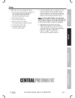
Setup

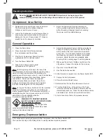
1.  Break in the new Air Compressor as follows: 

a.  Turn the Power Switch off and unplug the unit.   

Insert a male coupler (sold separately) 

into the female Quick Coupler and 

fully open all regulators and valves.

b.  Plug in the Power Cord.
c.  Turn the Power Switch ON.
d.  Let the unit run for 30 minutes.  

Air will expel freely through the Coupler.

e.  Turn the Power Switch OFF.
f.  Unplug the Power Cord and 

remove the male coupler.

2.  Connect a regulator valve, an inline shut off valve 

and a 1/4″ NPT air hose to the Quick Coupler 

(all sold separately).  The air hose must be long 

enough to reach the work area with enough extra 

length to allow free movement while working.

Note:


An in-line shutoff ball valve is an important 

safety device because it controls the air supply even 

if the air hose is ruptured.  The shutoff valve should 

be a ball valve because it can be closed quickly.

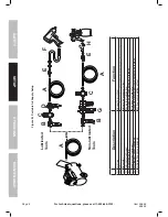
3.  Depending on the tool which you will be 

using with this compressor, you may need to 

incorporate additional components, such as an 

in-line oiler, a filter, or a dryer (all sold separately), 

as shown on Figure B on page 8 and 

Figure C on page 9.  Consult your air 

tool’s manual for needed accessories.

SAFETY

OPERA

TION

MAINTENANCE

SETUP

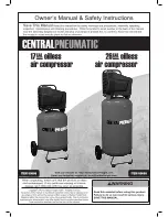
Summary of Contents for 26 GAL oilless air compressor

Page 1: ......

Page 2: ...potential personal injury hazards Obey all safety messages that follow this symbol to avoid possible injury or death Indicates a hazardous situation which if not avoided will result in death or serio...

Page 3: ...e tired or under the influence of drugs alcohol or medication A moment of inattention while operating a compressor may result in serious personal injury b Use personal protective equipment Always wear...

Page 4: ...OT RECOMMENDED If you choose to use an extension cord use the following guidelines Table A RECOMMENDED MINIMUM WIRE GAUGE FOR EXTENSION CORDS 120 VOLT NAMEPLATE AMPERES at full load EXTENSION CORD LEN...

Page 5: ...onductor with insulation having an outer surface that is green with or without yellow stripes is the equipment grounding conductor If repair or replacement of the electric cord or plug is necessary do...

Page 6: ...beginning of this manual including all text under subheadings therein before set up or use of this product TO PREVENT SERIOUS INJURY FROM ACCIDENTAL OPERATION Turn the Power Switch OFF and unplug the...

Page 7: ...hut off valve and a 1 4 NPT air hose to the Quick Coupler all sold separately The air hose must be long enough to reach the work area with enough extra length to allow free movement while working Note...

Page 8: ...lter Prevents dirt and condensation from damaging tool or workpiece C Regulator Adjusts air pressure to tool D Lubricator optional For air tool lubrication E Coupler and Plug Provides quick connection...

Page 9: ...e 3 4 minimum recommended Distributes air to branch lines F Ball Valve To drain moisture from system G Branch Air Line 1 2 minimum recommended Brings air to point of use H Air Hose Connects air to too...

Page 10: ...g wear on the compressor Note As long as the Power Switch is ON the operation of the Air Compressor is automatic controlled by an internal pressure switch The Compressor will turn on automatically whe...

Page 11: ...e damaged equipment If abnormal noise or vibration occurs have the problem corrected before further use Cleaning Maintenance and Lubrication 1 BEFORE EACH USE inspect the general condition of the air...

Page 12: ...ration 6 Reset circuit or replace fuse Check for low voltage conditions It may be necessary to disconnect other electrical appliances from the circuit or move the compressor to its own circuit 7 Use l...

Page 13: ...ate to less humid environment Safety Valve pops Safety valve needs service Pull on test ring of safety valve If it still pops replace Air leaks from pump or fittings Loose fittings Reduce air pressure...

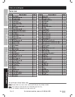
Page 14: ...ring Washer M3 4 37 Washer M3 4 38 Start Capacitor 1 39 Crankcase 1 40 Motor Cover 1 41 Rotor 1 42 Stator 1 43 Washer 203 1 44 Rear Seat 1 45 Centrifugal Switch 1 46 Capacitor Bracket 1 47 Bolt M5x12...

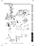
Page 15: ...7 18 19 25 27 26 20 21 22 24 60 59 63 64 62 76 78 77 79 80 83 82 81 84 85 57 58 87 56 86 56 58 88 89 92 91 93 95 90 75 74 67 66 69 70 50 53 54 52 5149 48 45 32 47 32 47 30 31 46 29 28 34 38 37 36 35 4...

Page 16: ...so the above limitation of exclusion may not apply to you THIS WARRANTY IS EXPRESSLY IN LIEU OF ALL OTHER WARRANTIES EXPRESS OR IMPLIED INCLUDING THE WARRANTIES OF MERCHANTABILITY AND FITNESS To take...

Reviews: