Page 5
SKU 45214
Operation
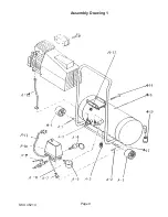
Warning!! Never attempt to adjust or remove Valve Air Outlet (#A-9). It is pre-set at 170
psi. Removal of valve voids warranty.
Warning!! Before using your compressor for the first time, fill with oil. Running the com-
pressor with low, or no oil, voids the warranty.
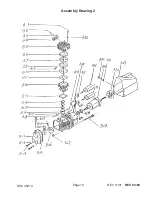
1. Carefully and slowly unscrew the Oil Dipstick (#B-19) from the oil reservoir. The assembly
is made of plastic and will break if you are too forceful.
2.
Check that oil reaches the full mark on the Oil Dipstick (#B-19). If not, fill with a standard,
non-detergent, 30-weight motor oil. Do not overfill. If overfilled, remove the drain plug and
drain appropriate amount.
Tool
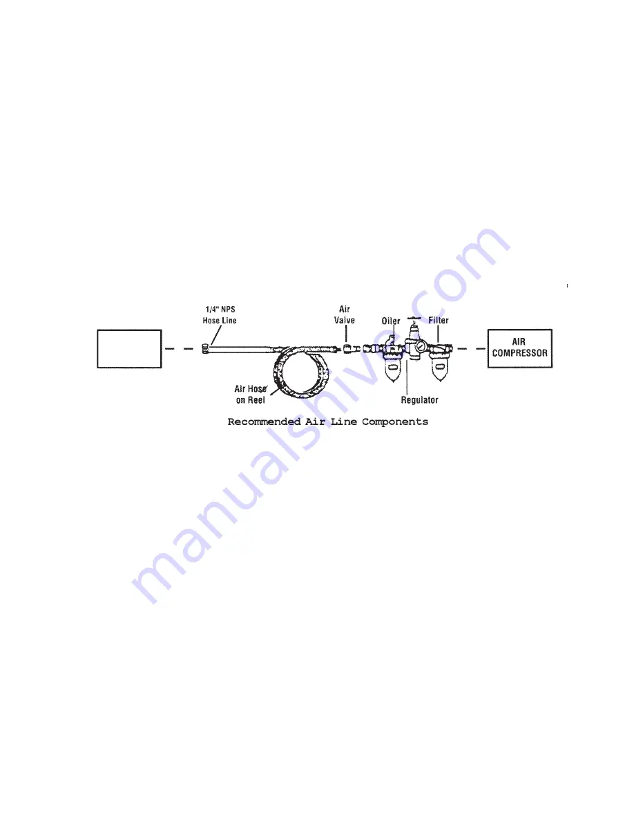
For best service, you should incorporate an oiler, regulator, and filter, in line, as shown in the
diagram below. Hoses, couplers, oilers, regulators, and filters are all available from Harbor
Freight Tools.
1. Conncect your air hose to the 1/4” NPT.
2. Safety pre-check:
a. Make sure the drain valve at the bottom of the tank is closed.
b.
Re-check the oil level.
c. Make sure the Valve Air Outlet (#A-9) is undamaged and functional.
3. Turn the Valve Air Outlet (#A-9) to the off position. In the off position, the handle is
perpendicular to the air hose fitting.
4. Turn on the compressor by pulling up the Air Pressure Switch (A-10). (To turn it off, push
the Air Pressure Switch (A-10) down.
5. Watch the Pressure Guage (#A-6) and allow the compressor to build up at least 80 psi.
6. After reaching 80 psi, open the Valve Air Outlet (#A-9) by turning it parallel to the air hose
fitting. This will pressurize the hoses and air tools. Check for air leaks and test your air tool.
7. When the Air Pressure Switch(A-10) is in the on position, the compressor is automati-
cally controlled by an internal pressure switch. The compressor automatically turns on when
the pressure drops to 80 psi, and turns back off when it reaches 110 psi.
Warning! Although the internal pressure switch is adjustable, changing the pressure
setting is not recommended; any change to the on/off pressure levels will cause addi-
tional stress to the motor, resulting in shortened motor life.
Note: If you need to quickly depressurize the air compressor, turn it off by pressing the Air
Pressure Switch (A-10) down, then, pull out the Safety Valve Ring (#A-4).
REV 02/04

