background image

AIR COMPRESSOR

AIR COMPRESSOR

AIR COMPRESSOR

AIR COMPRESSOR

AIR COMPRESSOR

3 HP

3 HP

3 HP

3 HP

3 HP, 12 GAL, V

, 12 GAL, V

, 12 GAL, V

, 12 GAL, V

, 12 GAL, V-HEAD

-HEAD

-HEAD

-HEAD

-HEAD

ASSEMBLY AND OPERATING INSTRUCTIONS

3491 Mission Oaks Blvd., Camarillo, CA 93011

Visit our Web site at http://www.harborfreight.com

Copyright © 2001 by Harbor Freight Tools

®

.  All rights reserved. No portion of

this manual or any artwork contained herein may be reproduced in any shape or
form without the express written consent of Harbor Freight Tools.

For technical questions and replacement parts, please call 1-800-444-3353

46168

REV 02/02

®

Summary of Contents for 46168

Page 1: ...IONS 3491 Mission Oaks Blvd Camarillo CA 93011 Visit our Web site at http www harborfreight com Copyright 2001 by Harbor Freight Tools All rights reserved No portion of this manual or any artwork cont...

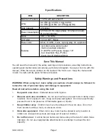
Page 2: ...invoice in a safe and dry place for future reference Safety Warnings and Precautions WARNING When using tool basic safety precautions should always be followed to reduce the risk of personal injury a...

Page 3: ...not in use 12 Remove adjusting keys and wrenches Check that keys and adjusting wrenches are removed from the tool or machine work surface before plugging it in 13 Avoid unintentional starting Be sure...

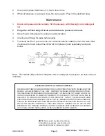
Page 4: ...mable liquids towards the compressor 25 Avoid body injury Never direct the air outlet at persons or animals Note Performance of this tool may vary depending on variations in local line voltage Exten s...

Page 5: ...d on operation is automatic and under the control of the internal pressure switch Adjusting Pressure Switch Caution The internal pressure switch is adjustable but changes to the pressure levels are no...

Page 6: ...ividually as replacement parts PLEASE READ THE FOLLOWING CAREFULLY THE MANUFACTURER AND OR DISTRIBUTOR HAS PROVIDEDTHE PARTS DIAGRAM INTHIS MANUAL AS A REFERENCE TOOL ONLY NEITHER THE MANUFACTURER NOR...

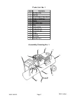
Page 7: ...ip Stick 3 On Off Pressure Power Switch 4 Pressure Relief Valve 5 Handle 7 Air Control Valve 8 Foot 9 Cord and Plug 10 Pressure Gauge 11 Water Spill Valve 12 Wheel 13 Air Tank 14 Fan Guide 15 Capacity...

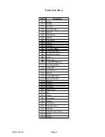
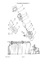
Page 8: ...der Gasket B03 Compressor Ring B04 Scraping Oil Ring B02 Piston B05 Piston Ring B06 Crankshaft Retainer C15 Connecting Rod C04 Crankshaft D33 Front Cover C24 Gasket C01 Crankshaft Case D25 Stator and...

Page 9: ...Page 9 SKU 46168 Assembly Drawing No 2...

Reviews: