background image

SKU 54700        For technical questions, please call 1-800-444-3353

PAGE 7

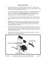
SAFETY (91)

TRIGGER (72, 74)

QUICK CONNECTOR

(1)

3.

The Nailer should not fire if the Safety (91) is not depressed against the work-
piece.

4.

Make sure the Trigger (72, 74) and Safety (91) move freely, without sticking - see
the illustration below.

5.

Connect the air supply to the tool at the Quick Connector (1).  Set the regulator at
the recommended 70 PSI to 100 PSI, and set not to go over the maximum 100
PSI.

6.

Test the tool by depressing the Safety (91) against the workpiece without pulling
the Trigger (72, 74).  The Tool must not cycle (fire).   If it cycles (fires), stop
immediately and have it repaired by a qualified service technician.

7.

Hold the tool away or off of the workpiece.  The Safety (91) of the tool should
return to its original position.  Squeeze the Trigger (72, 74).  The tool should not
cycle (fire). 
 If the tool fires, stop immediately and have it repaired by a qualified
service technician.

8.

Depress the Safety (91) against the workpiece and squeeze the Trigger (72, 74).
The tool must cycle (fire) only once.  Release the Trigger and squeeze it again.
The tool must cycle (fire) only once.  With the Trigger held, carefully lift the
nailer and press it against the workpiece again.  The tool must not cycle (fire).
If it fails to perform in the manner explained in bold, have it repaired by a qualified
service technician.

Summary of Contents for 54700

Page 1: ...at http www harborfreight com TO PREVENT SERIOUS INJURY READ AND UNDERSTAND ALL WARNINGS AND INSTRUCTIONS BEFORE USE Copyright 2004 by Harbor Freight Tools All rights reserved No portion of this manua...

Page 2: ...Do not expose to rain Keep work area well lit Do not use electrically powered tools in the presence of flammable gases or liquids 3 Keep children away Children must never be allowed in the work area D...

Page 3: ...with care Keep tools clean for better and safer performance Follow instructions for lubricating and changing accessories Inspect tool cords and air hoses periodically and if damaged have them repaired...

Page 4: ...oper size and type extension cord If an extension cord is required it must be of the proper size and type to supply the correct current to the compres sor without heating up Otherwise the extension co...

Page 5: ...contain preservatives such as copper chro mium arsenate CCA which can be toxic When stapling or nailing these materials extra care should be taken to avoid inhalation and minimize skin con tact WARNIN...

Page 6: ...The amount of air pressure effects how deep the nails staples will be driven It is suggested that you experiment on scrap material 4 Check the air connection for leaks and disconnect the Nailer Stapl...

Page 7: ...t cycle fire If it cycles fires stop immediately and have it repaired by a qualified service technician 7 Hold the tool away or off of the workpiece The Safety 91 of the tool should return to its orig...

Page 8: ...97 Loading Coil Nails ALWAYS WEAR ANSI APPROVED IMPACT SAFETY GOGGLES WHEN RELOADING OR DOING ANY OTHER MAINTENANCE ON THIS TOOL Other people in the work area must also wear ANSI approved impact safe...

Page 9: ...teeth of the Feed Pawl making sure the nail head fits in the slot in the upper portion of the Feed Pawl 5 Swing the Cannister Cover 69 closed Then close the Door 39 Make sure the Door latches securely...

Page 10: ...AL INJURY 3 Do not press the Nose of the Roofing Nailer against the work surface with extra force Allow the tool to do the work Always allow the tool to recoil off the work piece 4 Caution While worki...

Page 11: ...jammed nail usu ally from the Feed Pawl 36 area Replace the coil of nails into the Roofing Nailer Close the Cannister Cover 69 and Door 39 securely 4 Reconnect the Nailer to the air hose 5 Press the S...

Page 12: ...e accelerated wear to the internal seals 2 Inspect the air supply filter if present before each use and clean or replace as necessary Dirt and water in the air supply filter are major causes of pneuma...

Page 13: ...late 45 Feed Piston 78 O Ring 13 Head Cap 46 Piston Guide Stopper 79 O Ring 14 Compression Spring 47 Spring 80 Pin 15 Head Valve 48 Spring 81 Trigger Valve 16 O Ring 49 Spring Guide 82 Pin 17 O Ring 5...

Page 14: ...353 PAGE 14 ASSEMBLY DIAGRAM NOTE Some parts are listed and shown for illustration purposes only and are not available individually as replacement parts 95 MACHINE OIL NOT SHOWN 96 HEX WRENCH NOT SHOW...

Reviews: