background image

Page 12

For technical questions, please call 1-800-520-0882.

Engine for Item 56101 


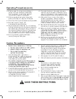
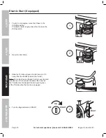
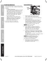
Electric Start (if equipped)

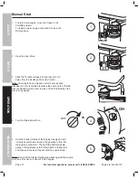
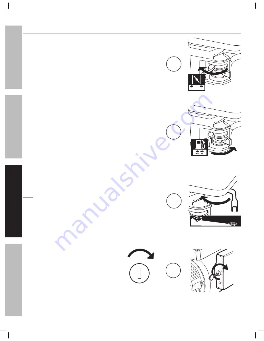
1.  To start a cold engine, move the Choke to the 

CHOKE position.  

To restart a warm engine, leave the Choke in the 

RUN position. 


2.  Open the Fuel Valve.

3.  Slide the Throttle or Speed Control Lever to 1/3 

away from the SLOW position (the “turtle”).

Note:

 Some tools have a Speed Control Lever located 

elsewhere on the tool which functions the same as 

the Throttle. Use the Speed Control Lever in place 

of the Throttle when the tool is so equipped.

4.  Turn the Engine Switch to START.

CHOKE RUN

1

2

3

ON

OFF

START

4

START

SAFETY

OPERA

TION

MAINTENANCE

SETUP

Summary of Contents for 56101

Page 1: ...hen unpacking make sure that the product is intact and undamaged If any parts are missing or broken please call 1 800 444 3353 as soon as possible Save This Manual Keep this manual for the safety warn...

Page 2: ...from windows doors and vents WARNING marking concerning Risk of Explosion IMPORTANT SAFETY INFORMATION General Safety Warnings WARNING Read all safety warnings and instructions Failure to follow the w...

Page 3: ...and NIOSH approved dust mask respirator under a full face shield along with steel toed work boots during use 11 People with pacemakers should consult their physician s before use Electromagnetic field...

Page 4: ...n the equipment These carry important information If unreadable or missing contact Harbor Freight Tools for a replacement 6 Have the equipment serviced by a qualified repair person using only identica...

Page 5: ...e tank to prevent corrosion 4 Safety Valve The Safety Valve automatically releases air if the Air Tank pressure exceeds the preset maximum In an emergency the ring can be pulled to relieve tank air pr...

Page 6: ...place with the Wing Nut Break In Compressor Break in the new Air Compressor as follows 1 Make sure the engine is off Open the air outlet valve on the left side of the tank 2 Check all fluid levels in...

Page 7: ...Prevents dirt and condensation from damaging tool or work piece C Regulator Adjusts air pressure to tool D Lubricator optional For air tool lubrication E Coupler and Plug Provides quick connection an...

Page 8: ...4 minimum recommended Distributes air to branch lines F Ball Valve To drain moisture from system G Branch Air Line 1 2 minimum recommended Brings air to point of use H Air Hose Connects air to tool I...

Page 9: ...use the air compressor unless all connections are air tight The extra air leaking out will cause the compressor to operate too often increasing wear on the compressor Before starting the Compressor a...

Page 10: ...ract fully and then pull it quickly Repeat until the engine starts Note Do not let the Starter Handle snap back against the engine Hold it as it recoils so it doesn t hit the engine For ELECTRIC START...

Page 11: ...ENANCE AND SERVICING section Note When maximum tank pressure is reached the compressor automatically disengages and the engine RPM drops down to idle speed The engine remains at idle until Air Tank pr...

Page 12: ...e in line Shutoff Valve 13 Bleed air from the tool then disconnect the tool 14 Open the Drain Valve at the bottom of the Tank to release any built up moisture and the internal tank pressure 15 Clean t...

Page 13: ...is Adding Oil 1 Oil Sight Glass 19 Crankcase 16 OVERFILL LOW FULL OIL LEVEL The oil level should be at the center of the full level on the Oil Sight Glass as shown above Add oil as needed to maintain...

Page 14: ...e Air Filter weekly to see if it needs replacement If working in dirty environments you may need to replace the filter more often To replace the Air Filter 1 Unthread the Wing Nut holding the Air Filt...

Page 15: ...1 Loose drive pulley or flywheel 2 Misaligned pulleys 3 Lack of oil in crankcase 4 Worn connecting rod 5 Worn wrist pin bushing 6 Worn bearings 7 Loose belts 1 Loose pulleys are a common cause of kno...

Page 16: ...rankcase 1 17 Oil Plug 1 18 Gasket 1 19 Oil Sight Glass 1 20 Drain Oil Bolt 1 21 Second Stage Cylinder Head 1 22 Bolt M12 40 4 23 Spring Washer 12 4 24 Gasket 1 25 Connecting Rod A 1 26 Connecting Rod...

Page 17: ...Page 17 For technical questions please call 1 800 444 3353 Item 56101 Pump Assembly Diagram SAFETY OPERATION MAINTENANCE SETUP...

Page 18: ...iption Qty 110 Bolt M10 50 4 111 Nut M10 4 112 Washer 8 1 113 Bolt M8 20 1 114 Bottom Plate 1 115 Nut M14 1 116 Spring Washer 14 1 117 Bracket 1 118 Threaded Rod 1 119 Bolt M6 20 1 120 Belt Guard Brac...

Page 19: ...Page 19 For technical questions please call 1 800 444 3353 Item 56101 Tank Assembly Diagram SAFETY OPERATION MAINTENANCE SETUP...

Page 20: ...tion of incidental or consequential damages so the above limitation of exclusion may not apply to you THIS WARRANTY IS EXPRESSLY IN LIEU OF ALL OTHER WARRANTIES EXPRESS OR IMPLIED INCLUDING THE WARRAN...

Page 21: ...vice may not be included When unpacking make sure that the product is intact and undamaged If any parts are missing or broken please call 1 800 520 0882 as soon as possible Save This Manual Keep this...

Page 22: ...ype 87 octane unleaded gasoline Capacity 1 Gallon Engine Oil Type SAE 10W 30 above 32 F 5W30 at 32 F or below Capacity 1 16 Quart Run Time 50 Load with full tank 3 hr Sound Level at 22 feet 108 dB Bor...

Page 23: ...afety goggles with side shields Read the manual before set up and or use WARNING marking concerning Risk of Hearing Loss Wear hearing protection Symbol Property or Statement WARNING marking concerning...

Page 24: ...ufficient weight bearing capacity when transporting the Engine 8 Secure the Engine on transport vehicles to prevent the tool from rolling slipping and tilting 9 Industrial applications must follow OSH...

Page 25: ...the equipment and do not use the equipment for a purpose for which it is not intended Service Precautions 1 Before service maintenance or cleaning a Turn the engine switch to its OFF position b Allow...

Page 26: ...vironmental Protection Agency and by the California Air Resources Board also known as CARB For warranty information refer to the last pages of this manual WARNING DO NOT INSTALL THIS ENGINE ON A VEHIC...

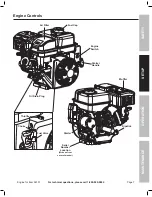
Page 27: ...20 0882 Engine for Item 56101 Engine Controls Starter Handle Oil Drain Plug Air Filter Fuel Valve Choke Fuel Cap Throttle Engine Switch Muffler Dipstick Starter Serial Number Location Write on front c...

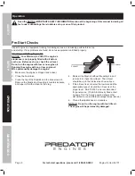
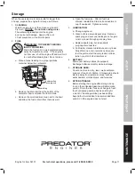
Page 28: ...engine oil WILL permanently damage the engine 1 Make sure the engine is stopped and is level 2 Close the Fuel Valve 3 Clean the top of the Dipstick and the area around it Remove the Dipstick by threa...

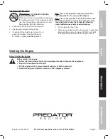
Page 29: ...ethanol E10 Do not use E85 ethanol Note Do not use gasoline that has been stored in a metal fuel container or a dirty fuel container It can cause particles to enter the carburetor affecting engine pe...

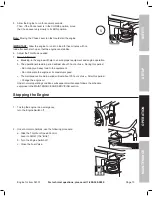
Page 30: ...ctions the same as the Throttle Use the Speed Control Lever in place of the Throttle when the tool is so equipped 4 Turn the Engine Switch on 5 Grip the Starter Handle of the Engine loosely and pull i...

Page 31: ...engine operation b The operational break in period will last about 3 hours of use During this period Do not apply a heavy load to the equipment Do not operate the engine at its maximum speed c The mai...

Page 32: ...position 2 Open the Fuel Valve 3 Slide the Throttle or Speed Control Lever to 1 3 away from the SLOW position the turtle Note Some tools have a Speed Control Lever located elsewhere on the tool which...

Page 33: ...d engine operation b The operational break in period will last about 3 hours of use During this period Do not apply a heavy load to the equipment Do not operate the engine at its maximum speed c The m...

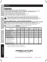
Page 34: ...Lubrication Schedule Note This maintenance schedule is intended solely as a general guide If performance decreases or if equipment operates unusually check systems immediately The maintenance needs o...

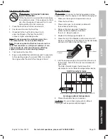
Page 35: ...ent FIRE do not start the engine while the smell of fuel hangs in the air Engine Oil Change CAUTION Oil is very hot during operation and can cause burns Wait for engine to cool before changing oil 1 M...

Page 36: ...om around spark plug 2 Using a spark plug wrench remove the spark plug 3 Inspect the spark plug If the electrode is oily clean it using a clean dry rag If the electrode has deposits on it polish it us...

Page 37: ...l valve After all fuel has drained reinstall the drain bolt and sediment cup if equipped Tighten securely 3 LUBRICATION a Change engine oil b Clean out area around spark plug Remove spark plug and pou...

Page 38: ...veral times to air out the chamber Reinstall spark plug and set Choke to CHOKE position 9 Replace Fuel Filter IGNITION SPARK RELATED 1 Spark plug cap not connected securely 2 Spark plug electrode wet...

Page 39: ...ore than 10 ethanol E15 E20 E85 etc 3 Test replace fuel tank cap 4 Have qualified technician service magneto 5 Secure spark plug cap Engine stops when under heavy load 1 Dirty air filter 2 Engine runn...

Page 40: ...ng 2 59 Rocker Valve 2 60 Nut Valve Adjusting 2 61 Nut Valve Lock 2 62 Spring Valve 2 63 Retainer Valve Spring 1 64 Starter Assy Recoil 1 65 Bolt 4 66 Shroud 1 67 Shroud Cylinder Body 1 68 Bolt 1 69 B...

Page 41: ...95 96 98 99 115 112 114 116 117 118 119 39 40 15 25 8 3 19 20 25 25 25 26 29 32 30 33 31 33 34 34 34 34 34 34 34 35 36 37 38 42 44 45 47 48 50 49 52 53 54 55 55 56 56 57 58 58 59 59 60 60 61 61 62 62...

Page 42: ...N OR WARRANTY OF ANY KIND TO THE BUYER THAT HE OR SHE IS QUALIFIED TO MAKE ANY REPAIRS TO THE PRODUCT OR THAT HE OR SHE IS QUALIFIED TO REPLACE ANY PARTS OF THE PRODUCT IN FACT THE MANUFACTURER AND OR...

Page 43: ...er Small Off Road Engine herein engine In California the engine must be designed built and equipped to meet the State s stringent anti smog standards Elsewhere within the United States new off road sp...

Page 44: ...hich are not authorized by HFT b Improper installation adjustment or repair of the engine or of any warranted part unless performed by an authorized warranty center c Failure to follow recommendations...

Reviews: