background image

Page 18

For technical questions, please call 1-888-866-5797.

ITEM 61454 


Sa

Fety

Setup

Opera

ti

O

n

Maintenance

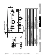
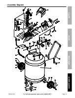
parts List and Diagram

parts List

record product’s Serial number Here: 
note:

 If product has no serial number, record month and year of purchase instead.

note:

 Some parts are listed and shown for illustration purposes only, 

and are not available individually as replacement parts.

part

Description

Qty

1

Cover

1

2

Elbow

1

3

Start Valve

1

4

Spring Washer M6

8

5

Screw M6 x 50

4

6

Air Filter

1

7

Cylinder Head

1

8

Head Gasket

1

9

Valve Plate

2

10

Metal Gasket

1

11

Valve

2

12

Valve Plate Gasket

1

13

Cylinder

1

14

Bolt M8 x 30

2

15

Spring Washer M8

3

16

Cylinder Gasket

1

17

Pin Ø 13 x 44

1

18

Compression Ring

2

19

Oil Ring

1

20

Wrist Pin Retainer

2

21

Piston

1

22

Connecting Rod

1

23

Screw M6 x 20

5

24

Hex Nut M6

3

25

Crank Shaft

1

26

O-Ring

2

26a Zip Tie

1

27

Capacitor

1

28

Screw M8 x 20

1

29

Capacitor Bracket

1

30

Hex Nut M8

1

31

Crank Case Cover

1

32

O-Ring

1

33

Oil Sight Glass

1

34

O-Ring

1

35

Drain Plug M5 x 10

1

36

O-Ring

1

37

Oil Plug

1

38

Crankcase Cover Gasket

1

39

Pump Crankcase

1

40

Washer M5

10

41

Screw M5 x 16

10

part

Description

Qty

42

Manual Overload Protector

1

43

Oil Seal

1

44

Bearing

1

45

Rotator

1

46

Bearing

1

47

Stator

1

48

Automatic Thermal Protector

1

49

End Cover

1

50

Fan

1

51

Circlip

1

51a Plain Washer 5

4

51b Spring Washer 5

4

51c Bolt M5 x 130

4

52

Connector

1

53

Tank Pressure Gauge

1

54

Pressure Switch

1

55

Unloader Tube

1

56

Nut

1

57

Ferrule

1

58

Check Valve

1

59

Ferrule

2

60

Nut

2

61

Exhaust Tube

1

62

Cooling Fin

1

63

Wheel

2

64

Bolt M12 x 55

2

64a Sleeve

2

64b Washer 12

2

65

Hex Nut M12

2

66

Drain Valve

1

67

Foot Pad

2

68

Washer

2

69

Screw M6 x 25

2

70

Tank

1

71

Bolt M6 x 10

4

72

Handle

1

73

Safety Valve

1

74

Pressure Regulator

1

75

Motor Cord

1

76

Quick Coupler

1

77

Output Pressure Gauge

1

78

Plug

1

Summary of Contents for 61454

Page 1: ...e for future reference When unpacking make sure that the product is intact and undamaged If any parts are missing or broken please call 1 888 866 5797 as soon as possible Copyright 2013 by Harbor Frei...

Page 2: ...ymbol It is used to alert you to potential personal injury hazards Obey all safety messages that follow this symbol to avoid possible injury or death Indicates a hazardous situation which if not avoid...

Page 3: ...use this compressor while you are tired or under the influence of drugs alcohol or medication A moment of inattention while operating a compressor may result in serious personal injury b Use personal...

Page 4: ...is greater 15 USE OF AN EXTENSION CORD IS NOT RECOMMENDED If you choose to use an extension cord use the following guidelines Table A RECOMMENDED MINIMUM WIRE GAUGE FOR EXTENSION CORDS 120 VOLT NAMEP...

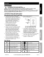
Page 5: ...risk of electric shock The conductor with insulation having an outer surface that is green with or without yellow stripes is the equipment grounding conductor If repair or replacement of the electric...

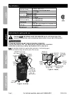
Page 6: ...n before set up or use of this product TO PREVENT SERIOUS INJURY FROM ACCIDENTAL OPERATION Turn the Power Switch OFF and unplug the Air Compressor from its electrical outlet before assembling or makin...

Page 7: ...ick Coupler and fully open all regulators and valves b Plug in the Power Cord c Turn the Power Switch ON d Let the unit run for 30 minutes Air will expel freely through the Coupler e Turn the Power Sw...

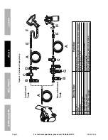
Page 8: ...r Hose Connects air to tool B Filter Prevents dirt and condensation from damaging tool or workpiece C Regulator Adjusts air pressure to tool D Lubricator optional For air tool lubrication E Coupler an...

Page 9: ...bration reduction E Main Air Line 3 4 minimum recommended Distributes air to branch lines F Ball Valve To drain moisture from system G Branch Air Line 1 2 minimum recommended Brings air to point of us...

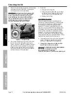
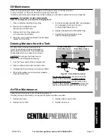
Page 10: ...above on the sight glass 3 To add oil a Remove the Oil Plug 37 b Using a funnel to avoid spills pour enough oil into the Pump Crankcase 39 to reach the full level in the Oil Sight Glass 33 c Replace t...

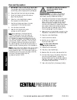
Page 11: ...pressor Area Set Up 1 Designate a work area that is clean and well lit The work area must not allow access by children or pets to prevent injury 2 Locate the Compressor on a flat level surface to ensu...

Page 12: ...switch The Compressor will turn on automatically when the air pressure drops to 95 PSI and will turn off automatically when the air pressure reaches 125 PSI WARNING TO PREVENT SERIOUS INJURY AND DEAT...

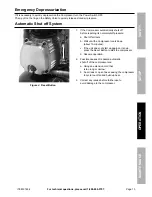
Page 13: ...f the Compressor automatically shuts off before reaching its normal cutoff pressure a Shut off all tools b Wait until the Compressor cools down about 10 minutes c If the unit does not start up again o...

Page 14: ...surfaces of the compressor with a clean cloth 3 WARNING If the supply cord of this compressor is damaged it must be replaced only by a qualified service technician Maintenance Schedule Following are g...

Page 15: ...regulations Draining Moisture from the Tank The Drain Valve is located under the Tank It must be used daily to release all trapped air and moisture from the Tank This will eliminate condensation which...

Page 16: ...that circuit matches compressor requirements 2 Drain oil and refill to proper level with recommended oil 3 Move compressor to a warmer location Check that recommended oil is in crankcase 4 Listen for...

Page 17: ...l surface Moisture in discharge air Too much moisture in air Install inline air filter dryer and or relocate to less humid environment Oil in discharge air 1 Crankcase oil too thin or crankcase overfi...

Page 18: ...ft 1 26 O Ring 2 26a Zip Tie 1 27 Capacitor 1 28 Screw M8 x 20 1 29 Capacitor Bracket 1 30 Hex Nut M8 1 31 Crank Case Cover 1 32 O Ring 1 33 Oil Sight Glass 1 34 O Ring 1 35 Drain Plug M5 x 10 1 36 O...

Page 19: ...Page 19 For technical questions please call 1 888 866 5797 ITEM 61454 Safety Setup Operation Maintenance Assembly Diagram a a b b...

Page 20: ...o the above limitation of exclusion may not apply to you THIS WARRANTY IS EXPRESSLY IN LIEU OF ALL OTHER WARRANTIES EXPRESS OR IMPLIED INCLUDING THE WARRANTIES OF MERCHANTABILITY AND FITNESS To take a...

Reviews: