background image

Page 4

For technical questions, please call 1-888-866-5797.

Item 62380 


Sa

Fety

Opera

ti

O

n

Maintenance

Setup

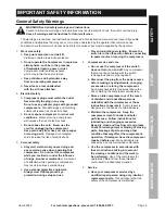
air compressor Safety Warnings

1� 

risk of fire or explosion - do not spray 

flammable liquid in a confined area or towards a 

hot surface.  Spray area must be well-ventilated.  

Do not smoke while spraying or spray where 

spark or flame is present.  arcing parts - keep 

compressor at least 20 feet away from explosive 

vapors, such as when spraying with a spray gun.

2� 

risk of bursting - do not adjust regulator higher 

than marked maximum pressure of attachment. 

Do not use at pressure greater than 150 PSI� 

3� 

risk of injury - do not direct air 

stream at people or animals.

4� 

Do not use to supply breathing air.

5� 

Do not leave compressor unattended 

for an extended period while plugged in.  

unplug compressor after working.

6� 

Keep compressor well-ventilated.  

Do not cover compressor during use.

7�  Drain Tank daily and after use�  Internal rust causes 

tank failure and explosion�

8�  Do not remove the valve cover or 

adjust internal components�

9�  Compressor head gets hot during operation�  

Do not touch it or allow children nearby 

during or immediately following operation�

10� Do not use the air hose to move the compressor�

11�  Release the pressure in the 

storage tank before moving� 

12� The use of accessories or attachments not 

recommended by the manufacturer may 

result in a risk of injury to persons�

13� All air line components, including hoses, pipe, 

connectors, filters, etc�, must be rated for a minimum 

working pressure of 200 PSI, or 150% of the 

maximum system pressure, whichever is greater�

14� USE OF AN EXTENSION CORD IS NOT 

RECOMMENDED�  If you choose to use an 

extension cord, use the following guidelines:

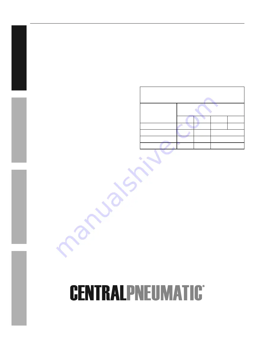
taBLe a:  recOMMenDeD MiniMuM Wire 

GauGe FOr eXtenSiOn cOrDS 

(120 VOLt)

naMepLate 

aMpereS

(at full load)

eXtenSiOn cOrD 

LenGtH

25′

50′

100′

150′

0 – 6

18

16

16

14

6�1 – 10

18

16

Do not use.

10�1 – 12

16

16

Do not use.

12�1 – 16

14

12

Do not use.

a�  Make sure your extension cord 

is in good condition�

b�  Be sure to use an extension cord which 

is heavy enough to carry the current your 

product will draw�  An undersized cord will 

cause a drop in line voltage resulting in loss 

of power and overheating�  Table A shows the 

correct size to use depending on cord length 

and nameplate ampere rating�  If in doubt, 

use the next heavier gauge�  The smaller 

the gauge number, the heavier the cord�

Summary of Contents for 62380

Page 1: ...ace for future reference When unpacking make sure that the product is intact and undamaged If any parts are missing or broken please call 1 888 866 5797 as soon as possible Copyright 2014 by Harbor Fr...

Page 2: ...symbol It is used to alert you to potential personal injury hazards Obey all safety messages that follow this symbol to avoid possible injury or death Indicates a hazardous situation which if not avo...

Page 3: ...rating this compressor Do not use this compressor while you are tired or under the influence of drugs alcohol or medication A moment of inattention while operating a compressor may result in serious p...

Page 4: ...t touch it or allow children nearby during or immediately following operation 10 Do not use the air hose to move the compressor 11 Release the pressure in the storage tank before moving 12 The use of...

Page 5: ...d consult their physician s before use Electromagnetic fields in close proximity to heart pacemaker could cause pacemaker interference or pacemaker failure 19 WARNING The brass components of this prod...

Page 6: ...risk of electric shock The conductor with insulation having an outer surface that is green with or without yellow stripes is the equipment grounding conductor If repair or replacement of the electric...

Page 7: ...fety Operation Maintenance Setup Specifications Electrical Rating 120VAC 60Hz 9 7A Air Outlet Size 1 4 18 NPT Air Pressure Shut off 150 PSI Restart 120 PSI Air Tank Capacity 6 Gallons Air Flow Capacit...

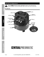
Page 8: ...Into Use Read the ENTIRE IMPORTANT SAFETY INFORMATION section at the beginning of this manual including all text under subheadings therein before set up or use of this product Functions Handle Safety...

Page 9: ...nnect a regulator valve an inline shut off valve and a 1 4 NPT air hose to the Quick Coupler all sold separately The air hose must be long enough to reach the work area with enough extra length to all...

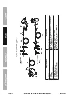
Page 10: ...ir Hose Connects air to tool B Filter Prevents dirt and condensation from damaging tool or workpiece C Regulator Adjusts air pressure to tool D Lubricator optional For air tool lubrication E Coupler a...

Page 11: ...ibration reduction E Main Air Line 3 4 minimum recommended Distributes air to branch lines F Ball Valve To drain moisture from system G Branch Air Line 1 2 minimum recommended Brings air to point of u...

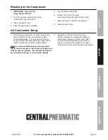
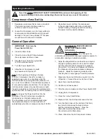
Page 12: ...not use the Air Compressor unless all connections are air tight the extra air leaking out will cause the compressor to operate too often increasing wear on the compressor Note As long as the Power Swi...

Page 13: ...c Shut off System 1 If the Compressor automatically shuts off before reaching its normal cutoff pressure a Shut off all tools Turn power switch off b Wait until the Compressor cools down 10 20 minutes...

Page 14: ...h 3 All the bearings in this tool are lubricated with a sufficient amount of high grade lubricant for the life to fht eunit under normal conditions Therefore no further lubrication of the bearings is...

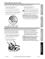
Page 15: ...ing to remove valve may cause serious personal injury 9 Turn off drain valve until completely closed Checking the Safety Valve DANGER Do not attempt to tamper with the safety valve Anything loosened f...

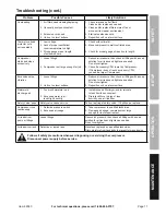
Page 16: ...eck that circuit matches compressor requirements 2 Move compressor to a warmer location 3 Listen for air leaking from valve If leaking replace with identical valve with same rating DO NOT SEAL OR TAMP...

Page 17: ...ory CFM you need a larger Compressor Excessive noise vibration 1 Loose fittings 2 Unit not on level surface 1 Reduce air pressure then check all fittings with a soap solution for air leaks and tighten...

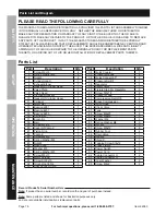
Page 18: ...M6 3 53 Screw M5x12 8 54 Rubber Foot 4 55 Drain Valve 1 56 Handle 1 57 Shroud 1 58 Tapping Screw St4x12 2 59 Press Fixture 1 60 Power Switch 1 61 Power Cord 1 62 Cable Connector U 2 63 Cable Connecto...

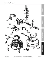
Page 19: ...Item 62380 Safety Operation Maintenance Setup Assembly Diagram 34 35 36 37 38 39 35 40 41 44 45 56 32 33 31 30 12 13 15 16 17 11 10 7 8 9 6 5 4 3 2 1 7 19 20 21 22 14 26 27 28 29 25 24 23 42 43 18 49...

Page 20: ...of incidental or consequential damages so the above limitation of exclusion may not apply to you THIS WARRANTY IS EXPRESSLY IN LIEU OF ALL OTHER WARRANTIES EXPRESS OR IMPLIED INCLUDING THE WARRANTIES...

Reviews: