background image

Page 9

For technical questions, please call 1-888-866-5797.

Item 62913 


SAFETY

Op

ERA

TION

M

AINTENANCE

INST

ALLA

TION

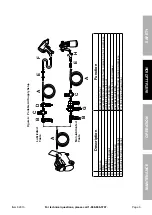
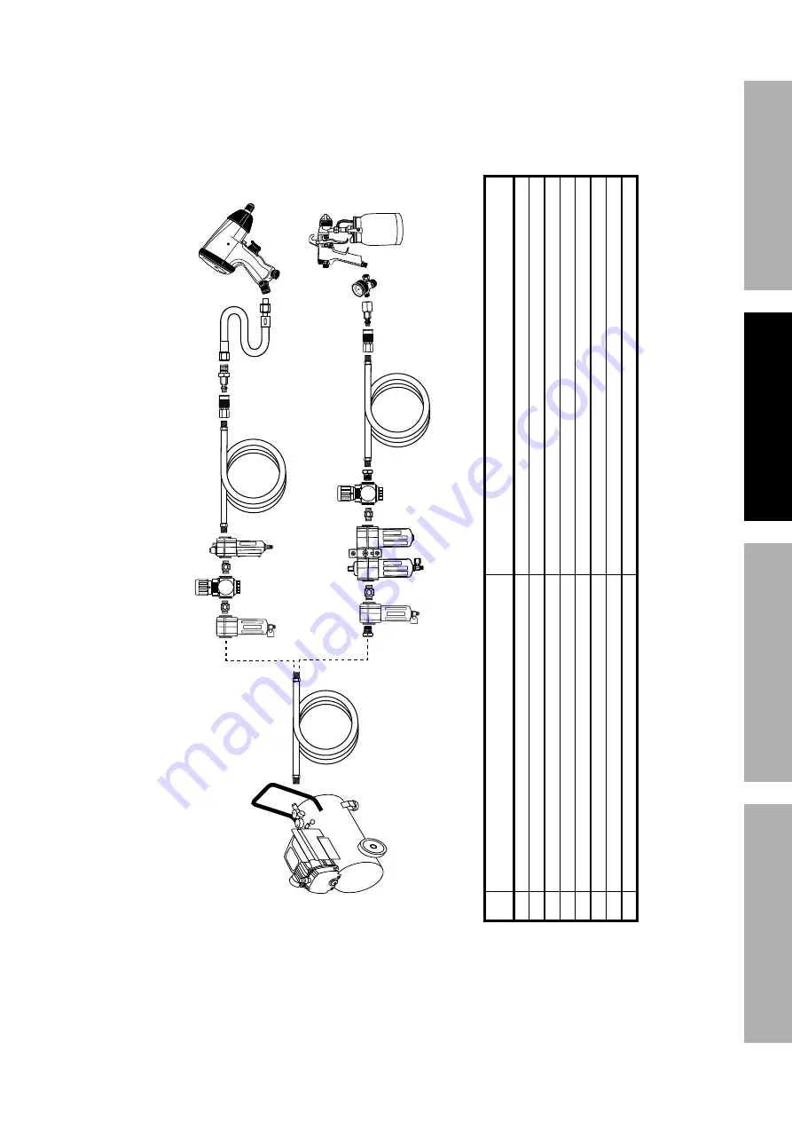
Figure

 A: 

 p

ortable 

Air Supply Setup

G

A

E

E

H

F

B

Non-lubricated   Tools

Lubricated  Tools

A

B

C

C

D

A

Description

Function

A

Air Hose

Connects air to tool

B

Filter

Prevents dirt and condensation from damaging tool or workpiece

C

Regulator

Adjusts air pressure to tool

D

Lubricator (optional)

For air tool lubrication

E

Coupler and Plug

Provides quick connection and release

F

Leader Hose (optional)

Increases coupler life

G

Air Cleaner / Dryer (optional)

Prevents water vapor from damaging workpiece

H

Air 

Adjusting V

alve (optional)

For fine tuning airflow at tool

Summary of Contents for 62913

Page 1: ...a poison you cannot see or smell NEVER use inside a home or garage EVEN IF doors and windows are open Only use OUTSIDE and far away from windows doors and vents When unpacking make sure that the prod...

Page 2: ...y alert symbol It is used to alert you to potential personal injury hazards Obey all safety messages that follow this symbol to avoid possible injury or death Indicates a hazardous situation which if...

Page 3: ...t may create sparks that can start fires around dry vegetation A spark arrestor may be required The operator should contact local fire agencies for laws or regulations relating to fire prevention requ...

Page 4: ...t may be suitable for one piece of equipment may become hazardous when used on another piece of equipment 9 Parts especially exhaust system components get very hot during use Stay clear of hot parts 1...

Page 5: ...lated Do not cover compressor during use 6 Add correct amount of compressor oil before first use and every use Operating with the incorrect amount of oil causes permanent damage and voids warranty To...

Page 6: ...l pipe thread straight RPM Revolutions Per Minute HP Horsepower WARNING marking concerning Risk of Eye Injury Wear ANSI approved safety goggles with side shields WARNING marking concerning Risk of Res...

Page 7: ...g parts and allows the large pulley to direct cooling air to the Air Pump 2 Oil Sight Glass The oil sight glass shows proper level of the oil Oil level should be at center of Sight Glass 3 Tank Drain...

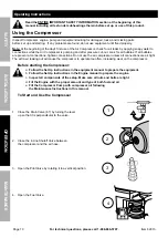
Page 8: ...e coupler sold separately into the female Quick Coupler and fully open all regulators and valves 2 Check all fluid levels in the engine and pump 3 Start the engine following the General Operating Inst...

Page 9: ...A Air Hose Connects air to tool B Filter Prevents dirt and condensation from damaging tool or workpiece C Regulator Adjusts air pressure to tool D Lubricator optional For air tool lubrication E Couple...

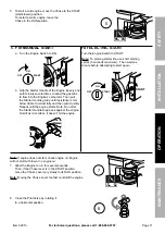
Page 10: ...ent at connections tighten connections Do not use the air compressor unless all connections are air tight The extra air leaking out will cause the compressor to operate too often increasing wear on th...

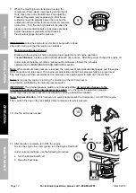
Page 11: ...pull it quickly Repeat until the engine starts Note Do not let the Starter Handle snap back against the engine Hold it as it recoils so it doesn t hit the engine For ELECTRIC START Turn the Engine Sw...

Page 12: ...ows the schedule explained in the MAINTENANCE AND SERVICING section Note When maximum tank pressure is reached the compressor automatically disengages and the engine RPM drops down to idle speed The e...

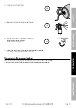
Page 13: ...in Valve at the bottom of the Tank to release any built up moisture and the internal tank pressure 15 Clean then store the Air Compressor inside a garage or another area that provides protection from...

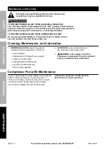
Page 14: ...ore further use Cleaning Maintenance and Lubrication 1 BEFORE EACH USE inspect the general condition of the air compressor Check for loose hardware misalignment or binding of moving parts cracked or b...

Page 15: ...e for this compressor please call Harbor Freight Tools customer service at 1 888 866 5797 for assistance WARNING To prevent serious injury from burns Do not add or change the oil while the compressor...

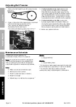
Page 16: ...be replaced 4 If either belt deflects too little loosen belts by loosening the Bolts on the Bottom Plate and moving the engine towards the other pulley slightly by turning the Nut 84 on the Threaded R...

Page 17: ...l 4 Replace pilot valve Excessive noise 1 Loose drive pulley or flywheel 2 Misaligned pulleys 3 Lack of oil in crankcase 4 Worn connecting rod 5 Worn wrist pin bushing 6 Worn bearings 7 Loose belts 1...

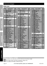
Page 18: ...over Gasket 1 41 Oil Sight Glass 1 42 Oil Sight Gasket 1 43 Drain Plug 1 44 Crankcase 1 45 Oil Plug Seal 1 46 Oil Plug 1 47 Bearing 1 48 Shaft Circlips 30 1 49 Shoulder Ring 1 50 Crankshaft 1 51 Woodr...

Page 19: ...Page 19 For technical questions please call 1 888 866 5797 Item 62913 Safety Operation Maintenance Installation Assembly Diagram...

Page 20: ...buse negligence or accidents repairs or alterations outside our facilities criminal activity improper installation normal wear and tear or to lack of maintenance We shall in no event be liable for dea...

Reviews: