background image

SKU 65903 

For technical questions, please call 1-800-444-3353.


Page 10

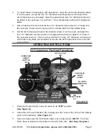
Turn the Pressure Adjustment Knob (6) 

4. 

counterclockwise

 all the way to its

 “OFF”


position.  

(See Figure E.)

Turn Lever on Air Outlet Valve (4) backward to 

5. 

closed

 position.  

(See Figure E.)

Attach an air hose (not included) to Air Outlet Valve.  Then, attach the other end of 

6. 

the air hose to the pneumatic tool that will be used.  

(See Figure E.)

To Start The Air Compressor:

Plug the Power Cord Plug (31) into the nearest 240 volt, grounded, electrical out-

1. 

let.
Rotate the Power Switch Lever (9) up to its

2. 

 “ON”

 position.  

(See Figure E.)

Turn the Pressure Adjustment Knob (6) 

3. 

clockwise

 about halfway to its

 “ON”

 posi-

tion.  

(See Figure E.)

Allow sufficient time for Tank Pressure Gauge (5A) to indicate at least 

4. 

80 PSi

.  

(See Figure E.)

Check to make sure the pneumatic tool which will be used is turned off and prop-

5. 

erly connected to air hose.
Once the Tank Pressure Gauge (5A) has reached at least 80 PSI, turn the Lever 

6. 

on the Air Outlet Valve (4) forward to its 

open

 position in order to supply air to the 

pneumatic tool. 

(See Figure E.)

If necessary, turn the Pressure Adjustment Knob (6) 

7. 

clockwise

 to increase air 

pressure to the pneumatic tool or 

counterclockwise

 to decrease air pressure to the 

pneumatic tool. The Outlet Pressure Gauge (5) shows the air pressure being sup-

plied to the tool. 

(See Figure E.)

To use The Air Tank Safety Release Valve:

The Safety Release Valve (3) is used when decompression is needed quickly and 

1. 

efficiently.  

(See Figure E.)

To decompress the Air Tank (32) pressure, rotate the Power Switch Lever (9) to the 

2. 

OFF position to turn off the Air Compressor.  

(See Figure E.)

Pull out on the Safety Release Valve Ring (3) to immediately release air pressure 

3. 

in the Air Tank (32).  

(See Figure E.)

To use The Overload Reset button:

The Air Compressor is equipped with an internal electrical circuit breaker which is 

1. 

designed to automatically shut off the Air Compressor in the event its Motor (14) 

becomes overheated. 

(See Figure E.)

Should the Air Compressor automatically shut off at a pressure less than 115 PSI, 

2. 

rotate the Power Switch Lever (9) down to its

 “OFF”

 position.  

(See Figure E.)

Summary of Contents for 65903

Page 1: ...Copyright 2008 by Harbor Freight Tools All rights reserved No portion of this manual or any artwork contained herein may be reproduced in any shape or form without the express written consent of Harbo...

Page 2: ...4 1 2 Diameter UNPACKING When unpacking check to make sure all the parts shown on the Parts List at the end of the manual are included If any parts are missing or broken please call Harbor Freight Too...

Page 3: ...to pull the Plug from an outlet Keep the Power Cord away from heat oil sharp edges or moving parts Replace damaged Power Cords immediately Damaged Power Cords increase the risk of electric shock An e...

Page 4: ...mpressors out of reach of children and other untrained persons 4 Compressors are dangerous in the hands of untrained users Maintain compressors with care Keep all components of this product clean 5 an...

Page 5: ...quipment from the unit before performing any services or maintenance Avoid injury Never direct the air jet at people or animals 6 Inspect safety valve daily 7 If the safety valve is not working proper...

Page 6: ...s before using this product Electromagnetic fields in close proximity to a heart pacemaker could cause interference to or failure of the pacemaker 20 WARNING The brass components of this product cont...

Page 7: ...ng Plug not included For safety purposes only a qualified certified electrician should attach a Plug to the Power Cord Never modify the Plug in any way To com ply with the National Electric Code and t...

Page 8: ...See Figure D Once the Oil Fill Cap 28 is removed fill the Air Compressor with a premium qual 3 ity 30 weight non detergent oil until the level of the oil rises to the midway point in the Oil Level In...

Page 9: ...g holes in its legs with the four pre drilled 1 2 holes in the concrete or wood Then use four minimum 3 long 1 2 diameter concrete an chor bolts or lag bolts not included to secure the Air Compressor...

Page 10: ...e Air Outlet Valve 4 forward to its open position in order to supply air to the pneumatic tool See Figure E If necessary turn the Pressure Adjustment Knob 6 7 clockwise to increase air pressure to the...

Page 11: ...Compressor press down on its Power Switch Lever 9 1 to turn off the unit See Figure E Disconnect the Power Cord Plug 31 from its electrical outlet 2 Turn on the pneumatic tool to expend all remaining...

Page 12: ...FILL HOLE PCV FILTER 41 OIL FILL CAP 28 3 Before each use Make sure to fill the Air Compressor with a premium quality 30 weight non detergent oil Running the Air Compressor with no oil or low oil will...

Page 13: ...er Cap Air Filter and Air Filter Bowl 39 Clean Air Filter with compressed air or if necessary re place old Air Filter with a new Air Filter Clean Air Filter Cap and Air Filter Bowl with a mild solvent...

Page 14: ...Belt 27 on Large Belt Wheel and Motor Pulley 14 9 See Figure H MOTOR PULLEY 14 LARGE BELT WHEEL 3 4 V BELT 27 FIGURE J 10 Slide the Motor 14 back toward its original position to tighten the tension o...

Page 15: ...normal wear and tear or to lack of maintenance We shall in no event be liable for death injuries to persons or property or for incidental contingent special or consequential damages arising from the u...

Page 16: ...month and year of purchase instead Note Some parts are listed and shown for illustration purposes only and are not avail able individually as replacement parts Part Description Qty 1 Flat Washer 8 4 2...

Page 17: ...SKU 65903 For technical questions please call 1 800 444 3353 Page 17 ASSEMBLY DIAGRAM REV 10g...

Reviews: