SKU 65903
For technical questions, please call 1-800-444-3353.
Page 9
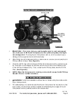
To mount the Air Compressor, with assistance, move the unit to the location where
3.
it is to be used. Using the four 1/2” diameter mounting holes on the feet of the
Air Compressor as a template, mark the spots where four 1/2” diameter holes will
be drilled in the concrete or wood floor. Then, temporarily set the Air Compressor
aside.
Use a masonry drill bit to drill the four 1/2” diameter holes (about 3”-4” deep) into
4.
the concrete. Make sure to blow out the concrete dust from the drilled holes.
Set the Air Compressor back to the location where it is to be used, and align the
5.
four 1/2” diameter mounting holes in its legs with the four pre-drilled 1/2” holes in
the concrete or wood. Then use four minimum 3” long, 1/2” diameter, concrete an-
chor bolts or lag bolts (not included) to secure the Air Compressor to the concrete
or wood floor.
OPERATiNG iNSTRuCTiONS
Air Compressor Pre-Start Procedures:
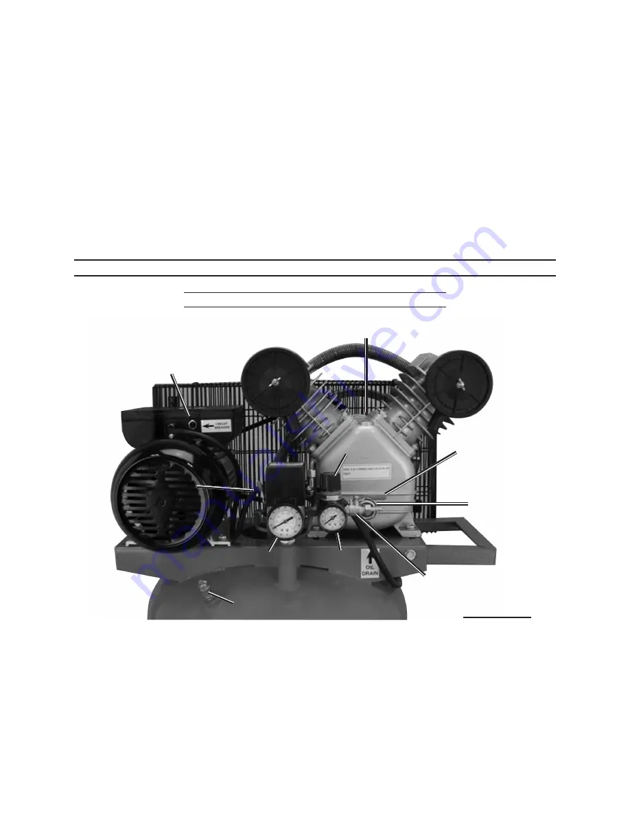
AiR
OuTLET VALVE
(4)
OiL FiLL CAP
(28)
OiL LEVEL
iNdiCATOR
(35)
OuTLET
PRESSuRE
GAuGE (5)
TANK
PRESSuRE
GAuGE (5A)
PRESSuRE
AdJuSTMENT
KNOb
(6)
POWER SWiTCH LEVER
(9)
AiR OuTLET
VALVE
LEVER
OVERLOAd
RESET
buTTON
(42)
SAFETY RELEASE VALVE (3)
FiGuRE E
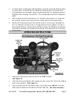
1. Press the Power Switch Lever (9) down to its
“OFF”
position.
(See Figure E.)
Check the Oil Level Indicator (35), making sure the level of the oil is at the midway
2.
point on the Indicator.
(See Figure E.)
Check to make sure the Tank Drain Valve (33) is fully closed.
3.
NOTE:
The Tank
Drain Valve is located on the
bottom
of the Air Tank (32).
(See Assy. diagram.)

