background image

Page 10

For technical questions, please call 1-800-444-3353.

Item 67450 


Figure

 E:  

Portable 

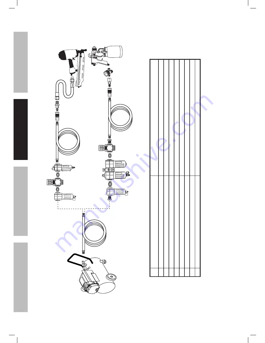
Air Supply Setup

G

A

E

E

H

F

B

Non-lubricated   Tools

Lubricated  Tools

A

B

C

C

D

A

Description

Function

A

Air Hose

Connects air to tool

B

Filter

Prevents dirt and condensation from damaging tool or workpiece

C

Regulator

Adjusts air pressure to tool

D

Lubricator (optional)

For air tool lubrication

E

Coupler and Plug

Provides quick connection and release

F

Leader Hose (optional)

Increases coupler life

G

Air Cleaner / Dryer (optional)

Prevents water vapor from damaging workpiece

H

Air 

Adjusting V

alve (optional)

For fine tuning airflow at tool

SAFETY

OPERA

TION

MAINTENANCE

SETUP

Summary of Contents for 67450

Page 1: ......

Page 2: ... could result in minor or moderate injury Addresses practices not related to personal injury Symbol Property or statement PSI Pounds per square inch of pressure CFM Cubic Feet per Minute flow SCFM Cubic Feet per Minute flow at standard conditions NPT National pipe thread tapered NPS National pipe thread straight WARNING marking concerning Risk of Eye Injury Wear ANSI approved safety goggles with s...

Page 3: ...es jewelry or long hair increases the risk of injury to persons as a result of being caught in moving parts c Avoid unintentional starting Be sure the trigger is released before connecting to the air supply Do not carry the tool with your finger on the trigger or connect the tool to the air supply with the trigger pressed d Do not overreach Keep proper footing and balance at all times Proper footi...

Page 4: ...Many accidents are caused by poorly maintained tools There is a risk of bursting if the tool is damaged h Use only accessories that are identified by the manufacturer for the specific tool model Use of an accessory not intended for use with the specific tool model increases the risk of injury to persons i Use only those fasteners listed in the Specifications chart of this manual Fasteners not iden...

Page 5: ...ays during firing causing them to exit the workpiece at an unexpected point causing personal injury 18 Transport tool safely Always disconnect air supply when moving the tool Carry the tool by the handle and avoid contact with the trigger 19 Hold tool away from head and body During operation the tool may kick back causing injury 20 Do not fire fasteners into a workpiece that has people utility lin...

Page 6: ... of vibration related injury 3 Wear suitable gloves to reduce the vibration effects on the user 4 Use tools with the lowest vibration when there is a choice between different processes 5 Include vibration free periods each day of work 6 Grip tool as lightly as possible while still keeping safe control of it Let the tool do the work 7 To reduce vibration maintain tool as explained in this manual If...

Page 7: ...chanism Type Full Sequential as shipped red Contact Trip trigger included Nail Type 0 120 Diameter Shank 3 4 1 3 4 Long Components and Controls Air Inlet Safety Nosepiece Shingle Guide Latch Magazine Trigger Exhaust Safety Nosepiece Also called the workpiece contact the Safety Nosepiece helps prevent the tool from firing unless it is pressed against an object SAFETY OPERATION MAINTENANCE SETUP ...

Page 8: ...s operation is safer and should be used whenever practical The RED Trigger enables contact trip bump fire operation This operation is more dangerous Only a skilled operator who is aware of the hazards and uses proper safe work practices should use contact trip bump fire operation 1 Remove Pin and Rubber Ring from current Trigger Rubber Ring Pin Trigger Lever Spring Figure A Trigger Components 2 Re...

Page 9: ...ssure and operate accidentally after the air supply is disconnected Note Air flow and therefore tool performance can be hindered by undersized air supply components 3 The air hose must be long enough to reach the work area with enough extra length to allow free movement while working 4 Release the tool s trigger and empty its magazine 5 Close the in line safety valve between the compressor and the...

Page 10: ...ter Prevents dirt and condensation from damaging tool or workpiece C Regulator Adjusts air pressure to tool D Lubricator optional For air tool lubrication E Coupler and Plug Provides quick connection and release F Leader Hose optional Increases coupler life G Air Cleaner Dryer optional Prevents water vapor from damaging workpiece H Air Adjusting Valve optional For fine tuning airflow at tool SAFET...

Page 11: ... 3 4 minimum recommended Distributes air to branch lines F Ball Valve To drain moisture from system G Branch Air Line 1 2 minimum recommended Brings air to point of use H Air Hose Connects air to tool I Filter Prevents dirt and condensation from damaging tool or workpiece J Regulator Adjusts air pressure to tool K Lubricator optional For air tool lubrication L Coupler and Plug Provides quick conne...

Page 12: ...ld only fire again if both Trigger and Safety Nosepiece are released first and then both are depressed again The Tool should not fire if the Safety Nosepiece is not pressed against an object Full Sequential Safety Trip Mechanism Testing Procedure TO PREVENT SERIOUS INJURY FROM ACCIDENTAL OPERATION Empty the tool before this procedure Point the tool at a piece of scrap wood when testing 1 Disconnec...

Page 13: ...ly 2 Empty the magazine of fasteners 3 Check that the Trigger and the Safety Nosepiece move freely without sticking 4 Connect the air supply to the tool and set within the Operating Air Pressure indicated on the Specification chart 5 Test the tool by pressing the Safety Nosepiece against the workpiece without pulling the Trigger The tool must not cycle fire If it cycles fires stop immediately and ...

Page 14: ...late 86 inside the Canister 82 Rotate the Adjuster Nut 88 to adjust the Platform to match the nail length A Between 3 4 and 1 Long Nails Use top setting B Between 1 and 1 1 4 Long Nails Use middle setting C Between 1 1 4 and 1 3 4 Long Nails Use bottom setting 3 Turn the Adjuster Nut 88 clockwise to raise the Adjuster Plate 86 until its edge aligns with the embossed nail size markings on the insid...

Page 15: ...t the tool receives sufficient unobstructed airflow CFM and increase the pressure PSI output of the regulator up to the maximum air pressure rating of this tool The adjuster can also be used to correct the firing depth CAUTION TO PREVENT INJURY FROM TOOL OR ACCESSORY FAILURE Do not exceed the tool s maximum air pressure rating If the tool still does not have sufficient force at maximum pressure an...

Page 16: ... the general condition of the tool Check for proper safety trip mechanism operation free safety nosepiece and trigger movement loose hardware or housing misalignment or binding of moving parts cracked or broken parts and any other condition that may affect its safe operation 2 Daily Air Supply Maintenance Every day perform maintenance on the air supply according to the component manufacturers inst...

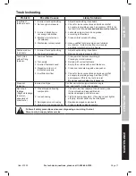
Page 17: ...l empty 3 Incorrect fasteners used 4 Magazine dirty or not lubricated properly 5 Insufficient air flow 1 Clear jammed fastener according to Clearing Jams instructions 2 Reload with correct fasteners 3 Empty then reload with correct fasteners 4 Clean and lubricate magazine and pusher 5 Check for loose connections and make sure that air supply is providing enough air flow CFM and pressure PSI to the...

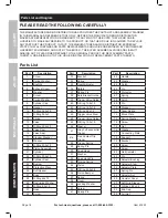
Page 18: ... O Ring 40 2x2 3 15 Valve Seal 16 Valve Seal 17 Stopper Washer 18 Washer 19 O Ring 43 3x3 5 20 Piston Assembly 21 Cylinder 22 O Ring 50 5x2 5 23 Cylinder Seal 24 Bumper 25 Protective Piece 26 Soft Spacer 27 Body 28 O Ring 46x1 3 29 Restrictive Washer 30 O Ring 8 3x1 8 31 Nose 32 Screw Part Description 33 Bracket 34 Spring 35 Depth Adjuster 36 Safety 37 Spring Pin 38 Safe Bracket Guide 39 Trigger V...

Page 19: ...oduct s Serial Number Here Note If product has no serial number record month and year of purchase instead Note Some parts are listed and shown for illustration purposes only and are not available individually as replacement parts Assembly Diagram SAFETY OPERATION MAINTENANCE SETUP ...

Page 20: ... so the above limitation of exclusion may not apply to you THIS WARRANTY IS EXPRESSLY IN LIEU OF ALL OTHER WARRANTIES EXPRESS OR IMPLIED INCLUDING THE WARRANTIES OF MERCHANTABILITY AND FITNESS To take advantage of this warranty the product or part must be returned to us with transportation charges prepaid Proof of purchase date and an explanation of the complaint must accompany the merchandise If ...

Reviews: