background image

Page 3

For technical questions, please call 1-800-444-3353.

SKU 67708 


SaVe tHIS manual

Keep this manual for the safety warnings 

and precautions, assembly, operating, 

inspection, maintenance and cleaning 

procedures.  Write the product’s serial number 

in the back of the manual near the assembly 

diagram (or month and year of purchase if 

product has no number).  Keep this manual 

and the receipt in a safe and dry place for 

future reference.

ImPortant SaFetY 

InFormatIon

In this manual, on the labeling, and 

all other information provided with 

this product:

  this is the safety alert 

symbol.  It is used to alert 

you to potential personal 

injury hazards.  obey all 

safety messages that follow 

this symbol to avoid possible 

injury or death.


danGer indicates a 

hazardous situation 

which, if not avoided, will result 

in death or serious injury.
 

WarnInG indicates a 

hazardous situation 

which, if not avoided, could 

result in death or serious injury.
 

cautIon, used with 

the safety alert 

symbol, indicates a hazardous 

situation which, if not avoided, 

could result in minor or moderate 

injury.


notIce is used to 

address practices not 

related to personal injury.
 

cautIon, without the 

safety alert symbol, is 

used to address practices not 

related to personal injury.

General compressor Safety 

Warnings

 WarnInG read all safety warnings 

and instructions.  Failure to follow 

the warnings and instructions may 

result in electric shock, fire and/or 

serious injury.   

Save all warnings and instructions 

for future reference.

1. 

Work area safety

a. 

keep work area clean and well lit.


Cluttered or dark areas invite accidents.

b. 

do not operate the compressor in 

explosive atmospheres, such as in 

the presence of flammable liquids, 

gases or dust.

  Compressor motors 

produce sparks which may ignite the 

dust or fumes.

c. 

keep children and bystanders away 

from an operating compressor.

2. 

electrical safety

a. 

compressor plugs must match the 

outlet.  never modify the plug in 

any way.  do not use any adapter 

plugs with grounded compressors.


Standard plugs and matching outlets 

will reduce risk of electric shock.

b. 

do not expose compressor to rain 

or wet conditions.

  Water entering 

a compressor will increase the risk of 

electric shock.

c. 

do not abuse the cord.  never 

use the cord for unplugging the 

Summary of Contents for 67708

Page 1: ...l rights reserved No portion of this manual or any artwork contained herein may be reproduced in any shape or form without the express written consent of Harbor Freight Tools Diagrams within this manu...

Page 2: ...ing 8 Instructions for putting into use 8 Functions 8 Assembly Mounting 9 Checking the Oil 10 General Operating Instructions 11 Compressor Area Set Up 11 General Operation 11 Emergency Depressurizatio...

Page 3: ...ided could result in minor or moderate injury NOTICE is used to address practices not related to personal injury CAUTION without the safety alert symbol is used to address practices not related to per...

Page 4: ...to operate it A compressor is dangerous in the hands of untrained users d Maintain the compressor Keep the compressor clean for better and safer performance Follow instructions for lubricating and cha...

Page 5: ...0 PSI or 150 of the maximum system pressure whichever is greater 15 USE OF AN EXTENSION CORD IS NOT RECOMMENDED If you choose to use an extension cord use the following guidelines RECOMMENDED MINIMUM...

Page 6: ...the plug will not fit the outlet have a proper outlet installed by a qualified electrician 110 120 V Grounded Compressors Compressors with Three Prong Plugs 1 In the event of a malfunction or breakdo...

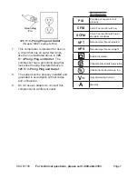
Page 7: ...plug illustrated above in 125 V 3 Prong Plug and Outlet 8 The outlet must be properly installed and grounded in accordance with all codes and ordinances 9 Do not use an adapter to connect this compres...

Page 8: ...ant Safety Information section at the beginning of this manual including all text under subheadings therein before set up or use of this product To prevent serious injury from accidental operation Tur...

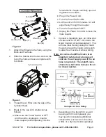
Page 9: ...minutes Air will expel freely through the Coupler e Turn the Power Switch OFF f Unplug the Power Cord and remove the male coupler 5 Connect a regulator valve an inline shut off valve and a 1 4 NPT air...

Page 10: ...hown above on the sight glass 3 To add oil a Remove the Oil Plug b Using a funnel to avoid spills pour enough oil into the Pump Crankcase to reach the full level in the Oil Sight Glass c Replace the O...

Page 11: ...ild up pressure until it cycles off Note At the beginning of the day s first use of the Air Compressor check for air leaks by applying soapy water to connections while the Air Compressor is pumping an...

Page 12: ...is necessary to quickly depressurize the Compressor turn the Power Switch OFF Then pull on the ring on the Safety Valve 73 to quickly release stored air pressure Automatic Shut off System 1 Reset But...

Page 13: ...rfaces of the compressor with a clean cloth 3 WARNING If the supply cord of this compressor is damaged it must be replaced only by a qualified service technician Maintenance Schedule Following are gen...

Page 14: ...the FULL level on the Oil Sight Glass f Replace and tighten the Oil Breather Plug g Discard the old oil according to local state and federal regulations Draining Moisture from the Tank The Drain Valve...

Page 15: ...Check that circuit matches compressor requirements 2 Drain oil and refill to proper level with recommended oil 3 Move unit to a warmer location Check that recommended oil is in crankcase 4 Listen for...

Page 16: ...needed Do not overtighten Excessive noise 1 Crankcase overfilled with oil or oil is incorrect thickness or type 2 Crankcase oil level too low 3 Loose or damaged belt guard 4 Loose fittings 5 Unit not...

Page 17: ...parts of the product In fact the manufacturer and or distributor expressly states that all repairs and parts replacements should be undertaken by certified and licensed technicians and not by the buy...

Page 18: ...Glass 1 34 O Ring 1 35 Drain Plug M5 x 10 1 36 O Ring 1 37 Oil Breather Plug 1 38 Crankcase Cover Gasket 1 39 Pump Crankcase 1 40 Washer M5 10 41 Screw M5 x 16 10 Part Description Qty 42 Manual Overl...

Page 19: ...Page 19 For technical questions please call 1 800 444 3353 SKU 67708 ASSEMBLY DIAGRAM...

Page 20: ...ecial or consequential damages arising from the use of our product Some states do not allow the exclusion or limitation of incidental or consequential damages so the above limitation of exclusion may...

Reviews: