background image

10

FEATURES

KNOW YOUR AIR COMPRESSOR

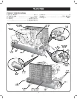
See Figure 1.

Before attempting to use this product, familiarize yourself 
with all operating features and safety rules.

DESCRIPTION

Your air compressor is aircooled, splash lubricated, belt-
driven, single stage.

DRIVE PULLEYS / FLYWHEELS

Drive pulleys and compressor flywheels must be properly 
aligned and tensioned to specifications. (

Refer to 

Belt 

Alignment & Adjustment

).

GUARDS

They must provide protection from moving parts while still 
allowing full air flow for cooling purposes.

CHECK VALVES

Check valves are designed to allow air to flow freely in 
one direction only. A properly sized check valve must be 
provided in the discharge line. 

Do not rely on a check 

valve to isolate a compressor from a pressurized tank 
or compressed air delivery system during maintenance 
procedures.

PRESSURE REGULATOR KNOB

The pressure regulator knob allows the operator to 
control the amount of air pressure being supplied to a tool 
(through the hose). A gauge is provided to indicate the air 
pressure. To adjust the amount of air pressure supplied:

  Pull up on the regulator knob to unlock it.
  Turn the knob clockwise to increase pressure - 

counterclockwise to decrease pressure.

  Push the knob down to lock it into position.

REGULATOR PRESSURE GAUGE

The current line pressure is displayed on the regulator  
pressure gauge. This pressure can be adjusted by rotating  
the pressure regulator knob.

SAFETY VALVES

Safety valves aid in preventing system failures by relieving 
system pressure when compressed air reaches a pre-determined 
pressure level. All air receivers must be equipped with an 
adequately sized safety valve. This type of valve is preset by the 
manufacturer and must not be modified in any way.
Safety valves are to be placed ahead of any potential 
blockage point which includes, but not limited to, shutoff 
valves, heat exchangers, pulsation dampeners, and 
discharge silencers. Ideally the safety valve should be 
threaded directly into the pressure point it is sensing, not 
connected with tubing or pipe, and always pointed away 
from any chance bystander. All tubing or piping added must 
be the same size as the safety valve opening or larger.

COMPRESSOR CONTROLS

Gasoline engine driven compressors are equipped with 
constant run controls and operate continuously until they 
are manually shut-off. During operation, air is compressed 
and delivered to the tanks for use. Once the demand for 
compressed air is satisfied, the in-line unloader (located 
in the compressor discharge line) is activated, causing the 
air delivered by the compressor to be discharged to the 
atmosphere, and allowing the engine to run at a lower speed. 
In this state, the system is considered to be “unloaded”. 
As the air stored in the tanks is used and the demand for 
compressed air returns, the unloader is deactivated, the 
engine runs at a higher speed, and the compressed air is 
once again delivered to the tanks for use.
When starting an engine driven unit with air pressure in the 
tank, flip the toggle on side of the pilot valve to the horizontal 
position. This will unload the compressor and allow the 
engine to start easier.
When the engine has run for a few minutes, flip the toggle 
back to its original position.

AIR FILTER

This compressor is equipped with an air filter to provide a 
clean air supply, an essential component to the satisfactory 
operation of your compressor.

   WARNING!

Excessive compressor RPM’s could cause a pulley or 
flywheel to shatter, possibly causing bodily harm or death. 
Do not operate the compressor above the recommended 
RPM as supplied by the factory.

   WARNING!

Guards must be fastened in place before starting the 
compressor. Always stop the unit before removing the 
guard.

   WARNING!

Safety valves must be provided to protect compressed 
air systems. Failure to provide properly sized pressure 
safety valves may cause property damage, severe 
personal injury or even death.

   WARNING!

Never locate the compressor where toxic, volatile or 
corrosive vapors, air temperatures exceeding 104°F, 
water, or extremely dirty air could be ingested. The 
compressor could be damaged by these atmospheres 
and result in injury or death.

Summary of Contents for 68140

Page 1: ...website at http www harborfreight com Read this material before using this product Failure to do so can result in serious injury SAVE THIS MANUAL For technical questions or replacement parts please c...

Page 2: ...eipt with purchase date for reference NOTICE 2 6 8LMW GSQTVIWWSV TYQT MW RSX IUYMTTIH ERH WLSYPH RSX FI YWIH XS WYTTP FVIEXLMRK UYEPMX EMV HHMXMSREP IUYMT QIRX SYPH FI RIGIWWEV XS TVSTIVP JMPXIV ERH T...

Page 3: ...ch is marked to comply with ANSI Z87 1 Additional safety protection will be required in some environments For example the working area may include exposure to a noise level which can lead to hearing d...

Page 4: ...ompress tank and allow water to drain and allow air compressor to become cool to the touch before servicing Turn pressure regulator knob fully counter clockwise after shutting off compressor When serv...

Page 5: ...pable of providing Never use the compressor without guards belt guard and never touch moving parts SPECIFIC SAFETY RULES Always follow all safety rules recommended by the manufacturer of your tool in...

Page 6: ...6 Do not adjust regulator to result in output pressure greater than marked maximum pressure of attachment Do not use at pressure greater than the rated maximum pressure of this compressor...

Page 7: ...I HEQEKI IJSVI FIKMRRMRK TS IV XSSP STIVEXMSR EP E W IEV WEJIX KSKKPIW WEJIX KPEWWIW MXL WMHI WLMIPHW SV E JYPP JEGI WLMIPH LIR RIIHIH I VIGSQQIRH MHI MWMSR 7EJIX 1EWO JSV YWI SZIV I IKPEWWIW SV WXERH...

Page 8: ...THE COMPRESSOR CYLINDER HEAD WHICH REMOVES IMPURITY FROM THE INTAKE AIR OF THE COMPRESSOR IR 4ANK YLINDRICAL COMPONENT WHICH CONTAINS THE COMPRESSED AIR HECK 6ALVE EVICE THAT PREVENTS COMPRESSED AIR F...

Page 9: ...ETY VALVE WHEEL TANK PRESSURE GAUGE REGULATOR PRESSURE GAUGE AIR OUTLET PRODUCT SPECIFICATIONS Engine Displacement 212 cc Air Tank Capacity 9 gal Air Pressure 135 PSI max Air Delivery 11 SCFM 40 PSI 9...

Page 10: ...ssure point it is sensing not connected with tubing or pipe and always pointed away from any chance bystander All tubing or piping added must be the same size as the safety valve opening or larger COM...

Page 11: ...perator s Manual 1 Replacement Parts List 1 INSTALLATION Air compressors should be located in an area that is dry clean well lighted and adequately ventilated Air supplied to the inlet filter must be...

Page 12: ...mpressor be used in an area where toxic volatile or corrosive agents are used or stored near the compressor CAUTION Unusual noise or vibration indicates a problem Do not operate the compressor until t...

Page 13: ...n a heated area before attempting to drain moisture from the tank s A correct use of the drain valve Verify that the compressor is turned off Disconnect the spark plug wire from the spark plug Reduce...

Page 14: ...APPLICATIONS Air compressors are utilized in a variety of air system applications Match hoses connectors air tools and accessories to the capabilities of the air compressor You may use this tool for...

Page 15: ...ATION STORAGE Shut off the engine Disconnect the spark plug wire from the spark plug and wrap around handle area to prevent damage when not in use Wearing safety glasses drain tank of air by pulling t...

Page 16: ...afety valves to make sure they are operating correctly Air pressure should escape when the ring is pulled refer to Fig 4 Check all pressurized components for rust cracking or leaking Immediately disco...

Page 17: ...the oil in a vessel If the oil does not drain out completely we recommend tilting the compressor slightly Dispose of the old oil at a drop off point for old oil When the oil has drained out re fit the...

Page 18: ...ler to move the motor pulley on the shaft Properly adjusted a 3 pound pressure applied to the belt between the motor pulley and the compressor flywheel will deflect the belt about 1 4 6mm Refer to Fig...

Page 19: ...min torque 22 Nm max torque 27 CLEANING THE INTAKE FILTER See Figure 12 The intake filter prevents dust and dirt being drawn in It is essential to clean this filter after at least every 100 hours in...

Page 20: ...crease unload pressure turn counterclockwise to decrease unload pressure Hold position with wrench and proceed to Step 4 Step 4 Tighten locknut clockwise with wrench Stabilize with back up wrench Sett...

Page 21: ...ssor won t operate Defective engine Replace or repair engine Lack of lubricant in compressor can cause serious damage to compressor Add lubricant refer to LUBRICATION Belt too tight or too loose Adjus...

Page 22: ...rectly sized Either use a smaller tool or a larger compressor Regulator not turned up to high enough pressure faulty regulator Turn the regulator to the proper setting replace faulty regulator Leaking...

Page 23: ...rsized for application Re evaluate application requirements re size compressor unit if necessary Insufficient lubrication Inspect for proper lubricant and amount refer to LUBRICATION Compressor runs b...

Page 24: ...imitation of exclusion may not apply to you THIS WARRANTY IS EXPRESSLY IN LIEU OF ALL OTHER WARRANTIES EXPRESS OR IMPLIED INCLUDING THE WARRANTIES OF MERCHANTABILITY AND FITNESS To take advantage of t...

Reviews: