20
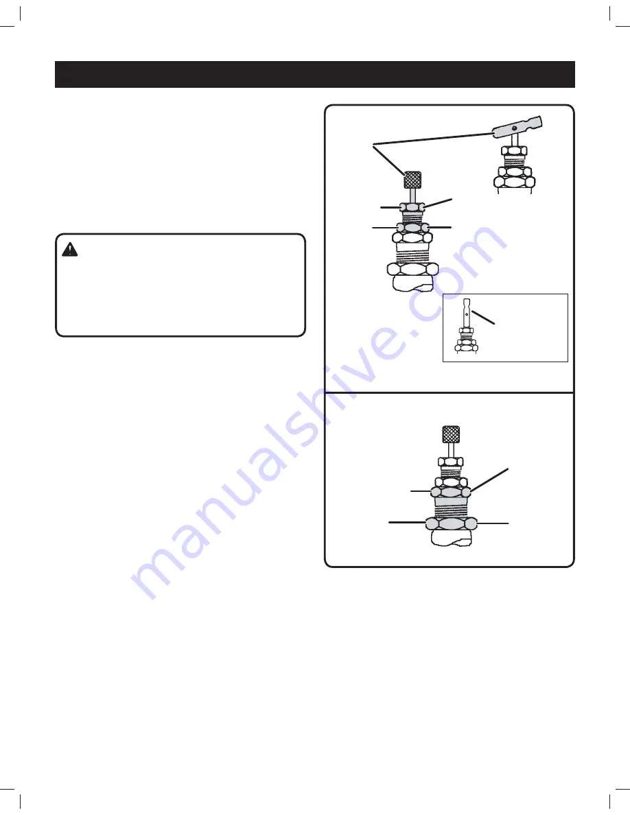
Fig. 14
MAINTENANCE
PILOT VALVE ADJUSTMENTS
See Figures 13 - 14.
All adjustments made to the pilot valve must be performed
by a qualified technician. The adjustments must be made
while the unit is operating, therefore, extreme caution must
be taken while working on the unit.
Observe all necessary precautions. Always use a back-
up wrench and make all differential and unload pressure
adjustments in very small increments (1/8 turn).
Setting Unload Pressure (Fig. 13)
Step 1.
Flip the toggle to the “RUN” position as shown,
or turn the knurled knob (if so equipped)
counterclockwise until it stops.
Step 2.
Loosen locknut (counterclockwise).
* Stabilize with back-up wrench!
Step 3.
Turn clockwise to increase unload pressure, turn
counterclockwise to decrease unload pressure.
Hold position with wrench and proceed to
Step 4
.
Step 4.
Tighten locknut (clockwise) with wrench.
* Stabilize with back-up wrench!
Setting Differential Pressure (Fig. 14)
Step 5.
Loosen locknut (counterclockwise).
* Stabilize with back-up wrench!
Step 6.
Turn clockwise to decrease the differential
pressure and counterclockwise to increase the
differential pressure. Hold position with wrench
and proceed to
Step 7
.
Step 7.
Tighten locknut (clockwise) with wrench.
* Stabilize with back-up wrench!
WARNING!
The pilot valve are set at the factory for maximum
efficiency. Adjustments to either component must be
performed by a qualified technician. Exceeding the
factory recommended maximum pressure will void the
warranty and may cause personal injury.
Step 1.
Step 2.
Step 3.
Step 4.
*
Step 5.
Step 6.
Step 7.
*
“Manual Unload”
position (Ref.)
Fig. 13

