background image

Page 7

For technical questions, please call 1-800-444-3353.

Item 69667 


SAFETY

OPERA

TION

MAINTENANCE

SETUP

Assembly/Mounting

1.   Attach the Wheels to the Tank, 

using the Bolts and Hex Nuts.

2.  Slide the Handle into the two slots on the top of 

the Tank and secure in place with four Bolts.

3.  Thread the Air Filter onto the side 

of the Cylinder Head.

4. 

Check and Fill oil according to section below.

5.  Break in the new Air Compressor as follows: 

a.  Turn the Power Switch off and unplug the unit.   

Insert a male coupler (sold separately) 

into the female Quick Coupler and fully 

open all regulators and valves.

b.  Plug in the Power Cord.
c.  Turn the Power Switch ON.
d.  Let the unit run for 30 minutes.  

Air will expel freely through the Coupler.

e.  Turn the Power Switch OFF.
f.  Unplug the Power Cord and 

remove the male coupler.

6.  Connect a regulator valve, an inline shut off valve 

and a 1/4″ NPT air hose to the Quick Coupler 

(all sold separately).  The air hose must be long 

enough to reach the work area with enough extra 

length to allow free movement while working.

Note:


An in-line shutoff ball valve is an important 

safety device because it controls the air supply even 

if the air hose is ruptured.  The shutoff valve should 

be a ball valve because it can be closed quickly.

7.  Depending on the tool which you will be 

using with this compressor, you may need to 

incorporate additional components, such as an 

in-line oiler, a filter, or a dryer (all sold separately), 

as shown on Figure C on page 8 and 

Figure D on page 9.  Consult your air 

tool’s manual for needed accessories.

Checking the Oil

1.  Check the oil level before operation.   

Fill the Pump Crankcase with 

SAE 30W, non-detergent, 

Air Compressor Oil (sold separately).

IMPORTANT:


Running the Air Compressor 

with no oil or low oil will cause damage to 

the equipment and void the warranty.

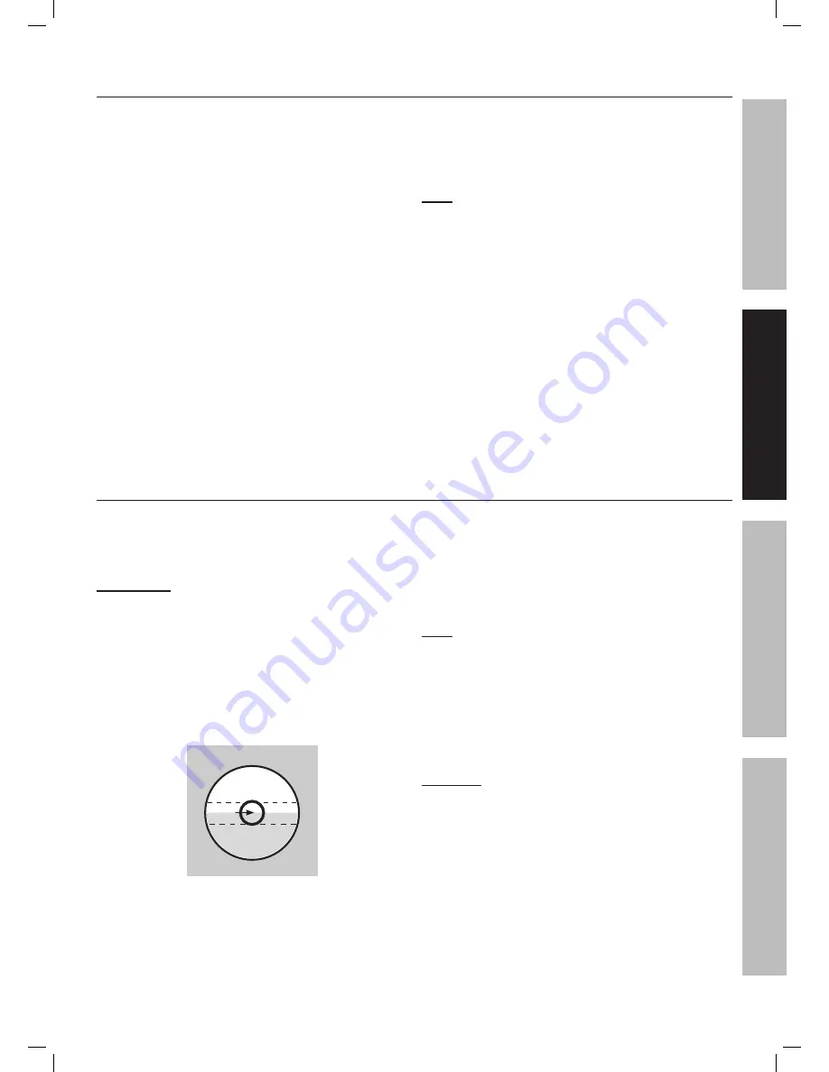
2.  The oil level should be at the center of the “full” level 

on the oil level sight glass, as shown in Figure B.   

Add oil as needed to maintain this level.   

Do not let the oil level go below the center dot 

(LOW as shown above) and do not overfill 

the oil so that it is above the center dot 

(OVERFILL as shown above) on the sight glass.

OVERFILL

LOW

FULL

Figure B:  Oil Sight Glass

3.  To add oil:

a.  Remove the Oil Plug.
b.  Using a funnel to avoid spills, pour enough 

oil into the Pump Crankcase to reach 

the “full” level in the Oil Sight Glass.

c.  Replace the Oil Plug.

Note:

 SAE 30W, non-detergent, 

Air Compressor Oil (sold separately) is 

recommended for use with this compressor.

4.  If uncertain which oil to use for this compressor, 

call Harbor Freight Tools customer service 

at 1-800-444-3353 for assistance.

5. 

Change the compressor oil after the first 

hour of use to remove any debris.

CAUTION! TO PREVENT INJURY FROM BURNS:  

Do not add or change the oil while 

the compressor is in operation.  

Allow the compressor to cool before replacing oil.

Summary of Contents for 69667

Page 1: ......

Page 2: ...symbol It is used to alert you to potential personal injury hazards Obey all safety messages that follow this symbol to avoid possible injury or death Indicates a hazardous situation which if not avoided will result in death or serious injury Indicates a hazardous situation which if not avoided could result in death or serious injury Indicates a hazardous situation which if not avoided could resul...

Page 3: ... use this compressor while you are tired or under the influence of drugs alcohol or medication A moment of inattention while operating a compressor may result in serious personal injury b Use personal protective equipment Always wear ANSI approved eye protection during setup and use c Prevent unintentional starting Ensure the switch is in the off position before connecting to power source or movin...

Page 4: ... hoses pipe connectors filters etc must be rated for a minimum working pressure of 150 PSI or 150 of the maximum system pressure whichever is greater 15 USE OF AN EXTENSION CORD IS NOT RECOMMENDED If you choose to use an extension cord use the following guidelines Table A RECOMMENDED MINIMUM WIRE GAUGE FOR EXTENSION CORDS 120 VOLT NAMEPLATE AMPERES at full load EXTENSION CORD LENGTH 25 50 100 150 ...

Page 5: ...in a risk of electric shock The conductor with insulation having an outer surface that is green with or without yellow stripes is the equipment grounding conductor If repair or replacement of the electric cord or plug is necessary do not connect the equipment grounding conductor to a live terminal 4 Check with a qualified electrician or service personnel if the grounding instructions are not compl...

Page 6: ...t the beginning of this manual including all text under subheadings therein before set up or use of this product TO PREVENT SERIOUS INJURY FROM ACCIDENTAL OPERATION Turn the Power Switch OFF and unplug the Air Compressor from its electrical outlet before assembling or making any adjustments to the compressor Note For additional information regarding the parts listed in the following pages refer to...

Page 7: ...ompressor you may need to incorporate additional components such as an in line oiler a filter or a dryer all sold separately as shown on Figure C on page 8 and Figure D on page 9 Consult your air tool s manual for needed accessories Checking the Oil 1 Check the oil level before operation Fill the Pump Crankcase with SAE 30W non detergent Air Compressor Oil sold separately IMPORTANT Running the Air...

Page 8: ...r Hose Connects air to tool B Filter Prevents dirt and condensation from damaging tool or work piece C Regulator Adjusts air pressure to tool D Lubricator optional For air tool lubrication E Coupler and Plug Provides quick connection and release F Leader Hose optional Increases coupler life G Air Cleaner Dryer optional Prevents water vapor from damaging work piece H Air Adjusting Valve optional Fo...

Page 9: ...bration reduction E Main Air Line 3 4 minimum recommended Distributes air to branch lines F Ball Valve To drain moisture from system G Branch Air Line 1 2 minimum recommended Brings air to point of use H Air Hose Connects air to tool I Filter Prevents dirt and condensation from damaging tool or work piece J Regulator Adjusts air pressure to tool K Lubricator optional For air tool lubrication L Cou...

Page 10: ...ns Do not use the Air Compressor unless all connections are air tight the extra air leaking out will cause the compressor to operate too often increasing wear on the compressor Note As long as the Power Switch is ON the operation of the Air Compressor is automatic controlled by an internal pressure switch The Compressor will turn on automatically when the air pressure drops to 95 PSI and will turn...

Page 11: ...ff before reaching its normal cutoff pressure a Shut off all tools b Wait until the Compressor cools down about 10 minutes c If the unit does not start up again on its own press the Reset Button to start the compressor d Resume operation 2 Possible causes of repeated automatic shut off of the compressor are a Using an extension cord that is too long or narrow b An air leak or open hose causing the...

Page 12: ...the supply cord of this compressor is damaged it must be replaced only by a qualified service technician Maintenance Schedule Following are general guidelines for maintenance checks of the Air Compressor Note The environment in which the compressor is used and the frequency of use can affect how often you will need to check the Air Compressor components and perform maintenance procedures Daily a C...

Page 13: ...with new SAE 30W non detergent Air Compressor Oil to the FULL level on the Oil Sight Glass 12 oz 6 Replace and tighten the Oil Breather Plug 7 Discard the old oil according to local state and federal regulations Draining Moisture from the Tank The Drain Valve is located under the Tank It must be accessed daily to release all trapped air and moisture from the Tank This will eliminate condensation w...

Page 14: ...k that circuit matches compressor requirements 2 Drain oil and refill to proper level with recommended oil 3 Move compressor to a warmer location Check that recommended oil is in crankcase 4 Listen for air leaking from valve If leaking replace with identical valve with same rating DO NOT SEAL OR TAMPER WITH SAFETY VALVE 5 Reduce air pressure then check all fittings with a soap solution for air lea...

Page 15: ...s or type 2 Crankcase oil level too low 3 Loose or damaged belt guard 4 Loose fittings 5 Unit not on level surface 1 Drain oil and refill to proper level with recommended oil 2 Add oil to proper level check for leaks 3 Replace belt guard 4 Reduce air pressure then check all fittings with a soap solution for air leaks and tighten as needed Do not overtighten 5 Reposition unit on a level surface Moi...

Page 16: ...TO THE BUYER THAT HE OR SHE IS QUALIFIED TO MAKE ANY REPAIRS TO THE PRODUCT OR THAT HE OR SHE IS QUALIFIED TO REPLACE ANY PARTS OF THE PRODUCT IN FACT THE MANUFACTURER AND OR DISTRIBUTOR EXPRESSLY STATES THAT ALL REPAIRS AND PARTS REPLACEMENTS SHOULD BE UNDERTAKEN BY CERTIFIED AND LICENSED TECHNICIANS AND NOT BY THE BUYER THE BUYER ASSUMES ALL RISK AND LIABILITY ARISING OUT OF HIS OR HER REPAIRS T...

Page 17: ...Page 17 For technical questions please call 1 800 444 3353 Item 69667 ...

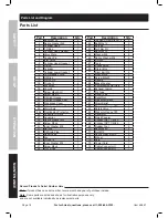
Page 18: ...1 24 Crankcase Cover Gasket 1 25 Motor Sets 1 25a Overloading Protector 1 26 Capacitor Fixture 1 27 Capacitor 1 28 Spring Washer M3 2 29 Screw M3x6 2 30 Inner Washer M8 1 31 Nut M8 1 32 Oil Drain Plug 1 33 Relief Valve 1 34 Fan 1 35 Circlip 14 1 36 Inner Washer M4 1 37 Screw M4x6 1 38 Oil Fill Cap 1 Part Description Qty 39 Tapping Screw St4 2x12 2 40 Bolt M5x12 2 41 Shroud 1 42 Air Filter Kit 1 43...

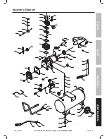
Page 19: ...Page 19 For technical questions please call 1 800 444 3353 Item 69667 SAFETY OPERATION MAINTENANCE SETUP Assembly Diagram ...

Page 20: ... so the above limitation of exclusion may not apply to you THIS WARRANTY IS EXPRESSLY IN LIEU OF ALL OTHER WARRANTIES EXPRESS OR IMPLIED INCLUDING THE WARRANTIES OF MERCHANTABILITY AND FITNESS To take advantage of this warranty the product or part must be returned to us with transportation charges prepaid Proof of purchase date and an explanation of the complaint must accompany the merchandise If ...

Reviews: