background image

SKU 90168 

For technical questions, please call 1-800-444-3353. 

Page 9

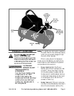
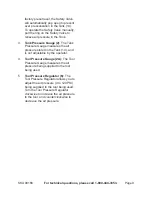
factory preset level, the Safety Valve 

will automatically pop open to prevent 

over pressurization in the Tank (14).  

To operate the Safety Valve manually, 

pull the ring on the Safety Valve to 

relieve air pressure in the Tank.

tank Pressure gauge (2): 

3. 

The Tank 

Pressure Gauge measures the air 

pressure stored in the Tank (14), and 

is 

not

 adjustable by the operator.

tool Pressure gauge (2a): 

4. 

The Tool 

Pressure Gauge measures the air 

pressure being supplied to the tool 

being used.

tool Pressure Regulator (6): 

5. 

The 

Tool Pressure Regulator allows you to 

adjust the air pressure (0 to 120 PSI) 

being supplied to the tool being used.  

Turn the Tool Pressure Regulator 

clockwise

 to 

increase

 the air pressure 

to the tool, and 

counterclockwise

 to 

decrease

 the air pressure.

Summary of Contents for 90168

Page 1: ...003 by Harbor Freight Tools All rights reserved No portion of this manual or any artwork contained herein may be reproduced in any shape or form without the express written consent of Harbor Freight T...

Page 2: ...indicates a hazardous situation which if not avoided could result in minor or moderate injury NOTICE is used to address practices not related to personal injury CAUTION without the safety alert symbo...

Page 3: ...able A shows the correct size to use depending on cord length and nameplate ampere rating If in doubt use the next heavier gage The smaller the gage number the heavier the cord Personal safety 3 Stay...

Page 4: ...ccordance f with these instructions taking into account the working conditions and the work to be performed Use of the compressor for operations different from those intended could result in a hazardo...

Page 5: ...ali fornia to cause cancer birth defects or other reproductive harm Some examples of these chemicals are Lead from lead based paints Crystalline silica from bricks and ce ment or other masonry product...

Page 6: ...tric shock The conductor with insulation having an outer surface that is green with or without yellow stripes is the equip ment grounding conductor If repair or replacement of the electric cord or plu...

Page 7: ...roper outlet Do not change the plug in any way Double insulated compressors may 2 be used in either of the 120 volt outlets shown in the preceding illus tration See Outlets for 2 Prong Plug Specificat...

Page 8: ...d in the following pages refer to the Assembly Diagram near the end of this manual Prior to using the Air Compressor make sure to familiarize yourself with its basic features and methods of operation...

Page 9: ...2 3 The Tank Pressure Gauge measures the air pressure stored in the Tank 14 and is not adjustable by the operator Tool Pressure Gauge 2A 4 The Tool Pressure Gauge measures the air pressure being supp...

Page 10: ...not overinflate any object Plug the Power Cord Plug 7 into the 5 nearest 120 volt grounded electrical outlet Turn the Power Switch 19 to its 6 AUTO or position Observe the Tank Pressure Gauge 7 2 and...

Page 11: ...r loose screws mis alignment or binding of moving parts damaged electrical wiring Tank air hoses accessories not included and any other condition that may af fect its safe operation AT END OF EACH WOR...

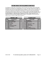
Page 12: ...READ THE FOLLOWING CAREFULLY The manufacturer and or distributor has provided the parts list and assembly diagram in this manual as a reference tool only Neither the manufacturer or distributor makes...

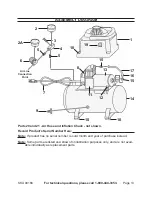
Page 13: ...1 10 10 9 7 Air Line Connection Point Parts 20 and 21 Air Hose and Inflation Chuck not shown Record Product s Serial Number Here Note If product has no serial number record month and year of purchase...

Page 14: ...ecial or consequential damages arising from the use of our product Some states do not allow the exclusion or limitation of incidental or consequential damages so the above limita tion of exclusion may...

Reviews: