background image

SKU 90234

PAGE 16

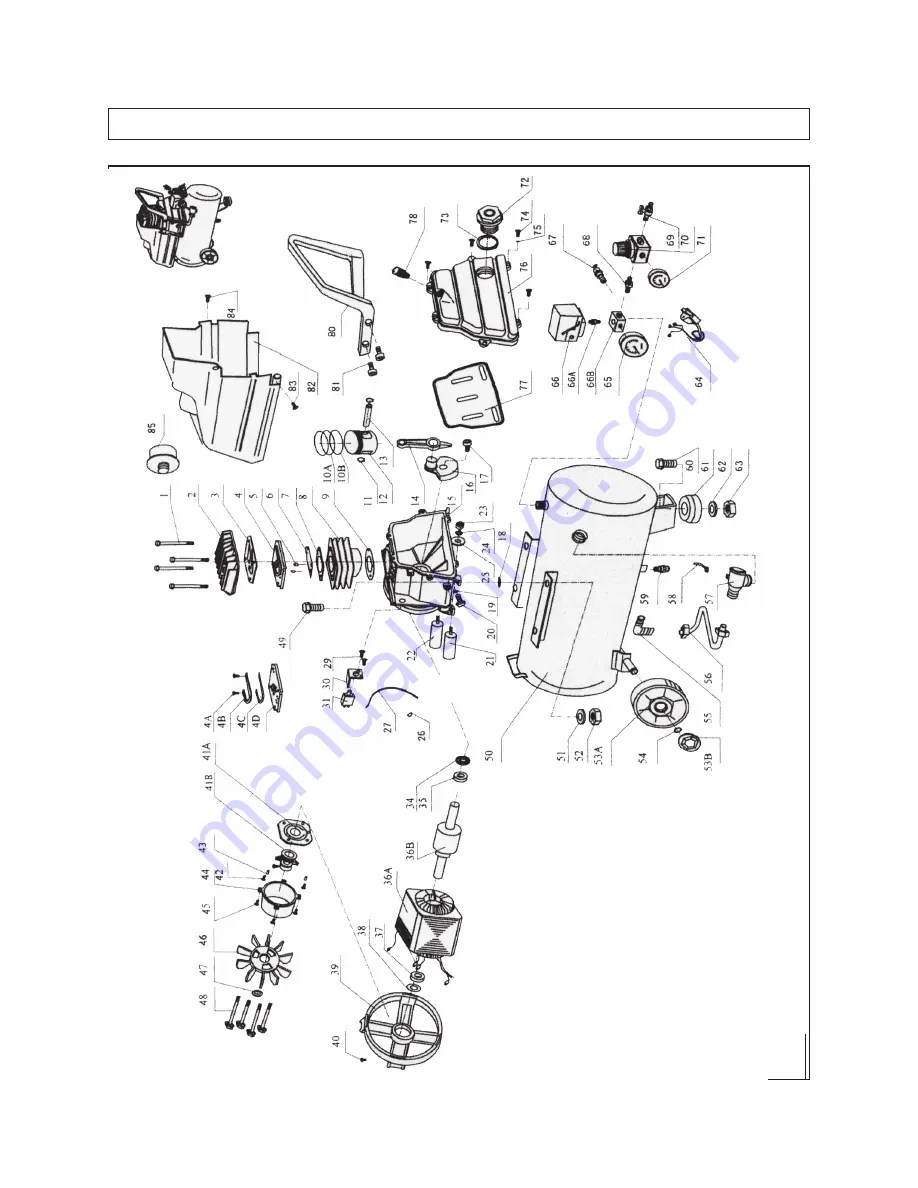
ASSEMBLY DIAGRAM

NO

TE:

 Some par

ts are listed and sho

wn f

or illustration pur

poses only

, and are not a

v

ailab

le individually

as 

replacement 

parts.

Summary of Contents for 90234

Page 1: ...our Web site at http www harborfreight com Copyright 2003 by Harbor Freight Tools All rights reserved No portion of this manual or any artwork contained herein may be reproduced in any shape or form w...

Page 2: ...ean and well lit Cluttered benches and dark areas invite accidents SKU 90234 PAGE 2 REV 04 04 m e t I n o i t p i r c s e D s t n e m e r i u q e R l a c i r t c e l E z H 0 6 V 0 2 1 d e t a R P H 3...

Page 3: ...ed outlet Do not change the plug in any way Double insulation eliminates the need for the three wire grounded power cord and grounded power supply system 6 Avoid body contact with grounded surfaces su...

Page 4: ...conditions TOOL USE AND CARE 15 Do not force the tool Use the correct tool for your application The correct tool will do the job better and safer at the rate for which it is designed 16 Do not use the...

Page 5: ...re in doubt as to whether the outlet is properly grounded Do not modify the power cord plug provided with the tool Never remove the grounding prong from the plug Do not use the tool if the power cord...

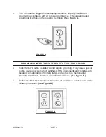
Page 6: ...ED TOOLS TOOLS WITH TWO PRONG PLUGS 4 Tools marked Double Insulated do not require grounding They have a special double insulation system which satisfies OSHA requirements and complies with the applic...

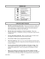
Page 7: ...acement 3 Use eye and hearing protection Always wear ANSI approved safety impact eye goggles and hearing protectors when using this product 4 Do not allow children to use or play with this product 5 S...

Page 8: ...be performed regularly by a qualified technician 18 Check for damaged parts Before using this product carefully check that it will operate properly and perform its intended function Check for damaged...

Page 9: ...factors which cannot be built into this product but must be supplied by the operator NOTE For additional information regarding the parts mentioned in the following pages refer to the Assembly Diagram...

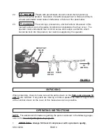
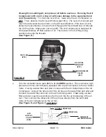
Page 10: ...Figure D 2 Turn the Air Outlet Valve part 69 to its CLOSED position Then connect a high pressure air hose not included equipped with a quick connector to the Air Outlet Valve If using a water filter...

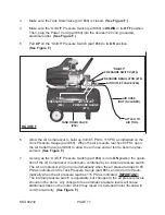
Page 11: ...uge part 65 When the air pressure reaches 85 PSI open the Air Outlet Valve part 69 to allow the air hose and air tool to become pres surized See Figure F 7 As long as the On Off Pressure Switch part 6...

Page 12: ...Off Pressure Switch part 66 Unplug the Power Cord part 64 from its electrical outlet Squeeze the trigger on the air tool being used to release all stored air pressure from the system and disconnect t...

Page 13: ...ing and if necessary filling the Air Compressor with oil see pages 9 and 10 of this manual INSPECTION AND MAINTENANCE 1 WARNING Always unplug the Air Compressor from its electrical outlet before perfo...

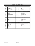
Page 14: ...r e d n i l y C 1 8 3 r e h s a W e v a W 1 A 0 1 g n i R r i A n o t s i P 2 9 3 r e v o C k c a B r o t o M e l E 1 B 0 1 g n i R l i O n o t s i P 1 0 4 t l o B 1 1 1 e l o H n I g n i R g n i n i...

Page 15: ...e b u T r e p p o C d a o l n U 1 3 7 l a e S w o d n i W l e v e L l i O 1 9 5 e v l a V n i a r D k n a T 1 4 7 t l o B 6 0 6 t l o B e l g n A x i S n I 1 5 7 r e h s a W g n i r p S 1 1 6 d a P r...

Page 16: ...SKU 90234 PAGE 16 ASSEMBLY DIAGRAM NOTE Some parts are listed and shown for illustration purposes only and are not available individually as replacement parts...

Reviews: