background image

SKU 90385

For technical questions, please call 1-800-444-3353.

Page 6

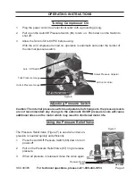
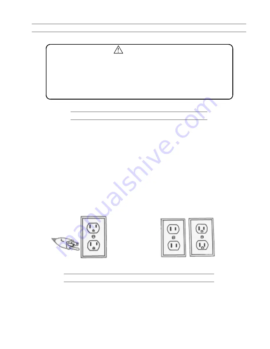
Figure A

Figure B

GROUNDING

WARNING!

Improperly connecting the grounding wire can result in the risk of electric 
shock.   Check with a qualfified electrician if you are in doubt as to whether the 
outlet is properly grounded.   Do not modify the power cord plug provided with 
the tool. Never remove the grounding prong from the plug.   Do not use the tool if 
the power cord or plug is damaged.   If damaged,   have it repaired by a service 
facility before use.   If the plug will not fit the outlet, have a proper outlet installed 
by a qualified electrician.

Grounded Tools:   Tools  with Three  Prong  Plugs

1.

Tools marked with “Grounding Required” have a three wire cord and three prong
grounding plug.  The plug must be connected to a properly grounded outlet.  If the tool
should electrically malfunction or break down, grounding provides a low resistance
path to carry electricity away from the user, reducing the risk of electric shock.  (See
Figure A.)

2.

The grounding prong in the plug is connected through the green wire inside the cord
to the grounding system in the tool.  The green wire in the cord must be the only wire
connected to the tool’s grounding system and must never be attached to an
electrically “live” terminal.  (See Figure A.)

3.

Your tool must be plugged into an appropriate outlet, properly installed and grounded
in accordance with all codes and ordinances.  The plug and outlet should look like
those in the following illustration.  (See Figure A.)

Double Insulated Tools: Tools with Two Prong Plugs

4.

Tools marked “Double Insulated” do not require grounding.  They have a special
double insulation system which satisfies OSHA requirements and complies with the
applicable standards of Underwriters Laboratories, Inc., the Canadian Standard
Association, and the National Electrical Code.  (See Figure B on page 6.)

5.

Double insulated tools may be used in either of the 120 volt outlets shown in the
preceding illustration.  (See Figure B on page 6.)

Summary of Contents for 90385

Page 1: ...NS 3491 MISSION OAKS BLVD CAMARILLO CA 93011 VISIT OUR WEB SITE AT HTTP WWW HARBORFREIGHT COM Copyright 2003 by Harbor Freight Tools All rights reserved No portion of this manual or any artwork contai...

Page 2: ...ance procedures parts list and diagram Keep your invoice with this manual Write the invoice number on the inside of the front cover Keep the manual and invoice in a safe and dry place for future refer...

Page 3: ...minates the need for the three wire grounded power cord and grounded power supply system 8 Do not abuse the Power Cord Never use the Power Cord to carry the tools or pull the Plug from an outlet Keep...

Page 4: ...ols out of reach of children and other untrained persons Tools are dangerous in the hands of untrained users 20 Maintain tools with care Keep cutting tools sharp and clean Properly maintained tools wi...

Page 5: ...om lead based paints crystalline silica from bricks and cement or other masonry products arsenic and chromium from chemically treated lumber Your risk from these exposures varies depending on how ofte...

Page 6: ...stance path to carry electricity away from the user reducing the risk of electric shock See Figure A 2 The grounding prong in the plug is connected through the green wire inside the cord to the ground...

Page 7: ...any parts are missing or broken please call Harbor Freight Tools at the number on the cover of this manual as soon as possible In addition this unit is packed with a rubber block to help prevent dama...

Page 8: ...in the Oil Plug being careful not to strip the plastic threads Hose Connections 1 Close the Air Control Valve 69 right or left 2 Connect the high pressure air hose to the air outlet The outlet is 1 4...

Page 9: ...but changes to the pressure levels are not recommended any change to the automatic On Off pressure levels will cause additional stress on the motor which may result in shortened motor life Using the P...

Page 10: ...RS AND PARTS REPLACE MENTS SHOULD BE UNDERTAKEN BY CERTIFIED AND LICENSED TECHNICIANS AND NOT BY THE BUYER THE BUYER ASSUMES ALL RISK AND LIABILITY ARISING OUT OF HIS OR HER REPAIRSTO THE ORIGINAL PRO...

Page 11: ...SIX ANGLE BOLT 1 59 UNLOAD WATER VALVE 1 18 RUBBER WASHER 4 60 BOLT 1 19 O RING 1 61 RUBBER FOOT PAD 1 20 BOLT 1 62 FLAT WASHER 1 21 STARTING CAPACITOR 1 63 BOLT 1 22 RUNNING CAPACITOR 1 64 ELE CABLE...

Page 12: ...SKU 90385 For technical questions please call 1 800 444 3353 Page 12 ASSEMBLY DRAWING...

Reviews: