background image

SKU 93351 

For technical questions, please call 1-800-444-3353.


Page 8

GROUNDING

GROUNDED TOOLS: TOOLS WITH THREE PRONG PLUGS 

1. 

Tools marked with “Grounding Required” have a three wire cord and three prong   
grounding plug.  The plug must be connected to a properly grounded outlet.  If    
the tool should electrically malfunction or break down, grounding provides a low   
resistance path to carry electricity away from the user, reducing the risk of elec-
tric shock.  

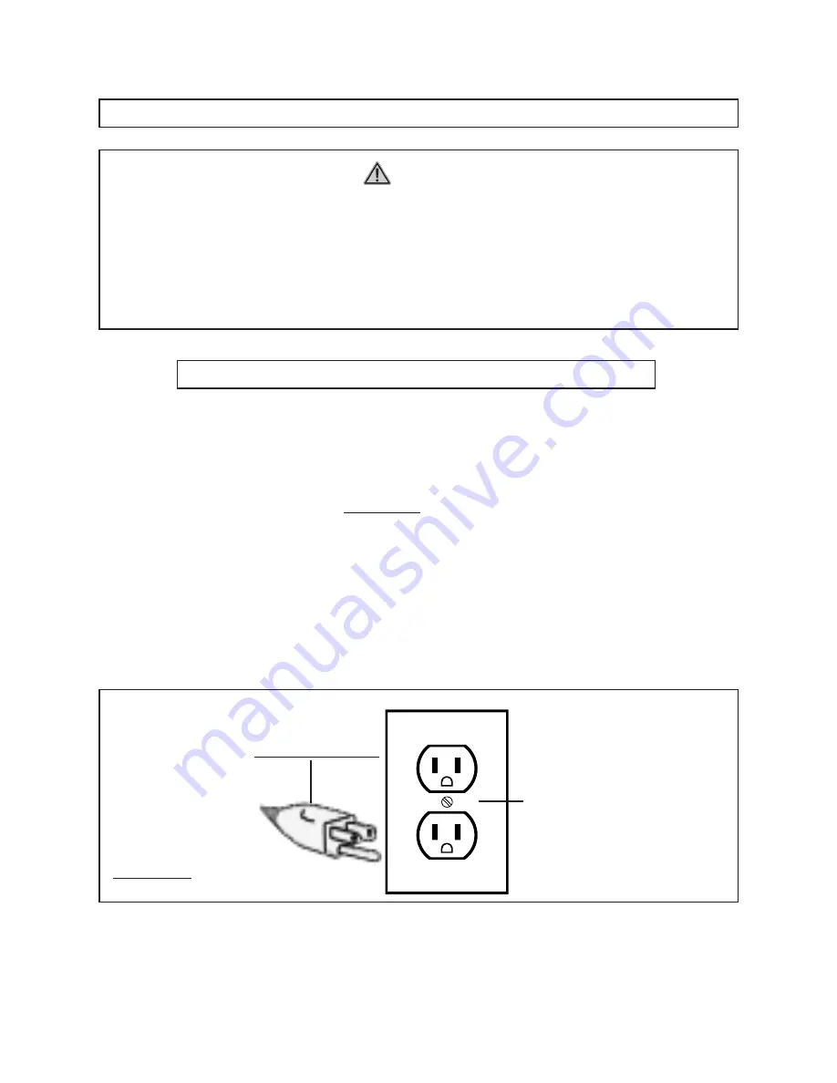
(See Figure B, next page.)

2. 

The grounding prong in the plug is connected through the green wire inside the    
cord to the grounding system in the tool.  The green wire in the cord must be the   
only wire connected to the tool’s grounding system and must never be attached    
to an electrically “live” terminal.  

(See Figure B.)

3. 

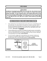
Your tool must be plugged into an appropriate outlet, properly installed and  


grounded in accordance with all codes and ordinances.  The plug and outlet  


should look like those in the following illustration.  

(See Figure B.)

120 VOLT,

GROUNDED,

ELECTRICAL OUTLET

THIS PRODUCT

USES A

3-PRONG PLUG

FIGURE B

WARNING!

Improperly connecting the grounding wire can result in the risk of electric shock.  
Check with a qualified electrician if you are in doubt as to whether the outlet is 
properly grounded.  Do not modify the power cord plug provided with the tool.  
Never remove the grounding prong from the plug.  Do not use the tool if the power 
cord or plug is damaged.  If damaged,  have it repaired by a service facility before 
use.  If the plug will not fit the outlet, have a proper outlet installed by a qualified 
electrician.

Summary of Contents for 93351

Page 1: ...L WARNINGS AND INSTRUCTIONS BEFORE USE Do to continuing improvements actual product may differ slightly from the product described herein WARNING Your Warranty Is Voided If A You do not put compressor...

Page 2: ...s Do not operate power tools in explosive atmospheres such as in the presence of flammable liquids gases or dust Power tools create sparks which may ignite the dust or fumes Keep bystanders children a...

Page 3: ...There is an increased risk of electric shock if your body is grounded 7 Do not expose power tools to rain or wet conditions Water entering a power tool will increase the risk of electric shock 8 Do n...

Page 4: ...measures reduce the risk of starting the tool accidentally Store idle tools out of reach of children and other untrained persons Tools are dangerous in the hands of untrained users Maintain tools with...

Page 5: ...using the Air Compressor Maintain a safe working environment Keep the work area well lit Make sure there is adequate surrounding workspace Always keep the work area free of ob structions grease oil t...

Page 6: ...e appropriate capacity Do not use any tool or equipment that does not operate from 85 PSI to 110 PSI Drain the Air Compressor every day Do not allow excessive moisture to build up inside the Air Compr...

Page 7: ...cts and other reproductive harm California Health Safety Code 25249 5 et seq WARNING People with pacemakers should consult their physician s before using this product Operation of electrical equipment...

Page 8: ...em and must never be attached to an electrically live terminal See Figure B 3 Your tool must be plugged into an appropriate outlet properly installed and grounded in accordance with all codes and ordi...

Page 9: ...rds of Underwriters Laboratories Inc the Canadian Standard Association and the National Electrical Code See Figure C 5 Double insulated tools may be used in either of the 120 volt outlets shown in the...

Page 10: ...let prior to assembling the Compressor or making adjustments to the unit To Attach The Handle And Wheels 1 To attach the Handle 50A to the Tank 50 of the Air Compressor align the two mounting holes in...

Page 11: ...bsequent use check the oil level Never run the Compressor with low or no compressor oil Running the Compres sor with low or no oil will permanently damage the unit Note Crankcase oil capacity is 25 3...

Page 12: ...0 to provide the PSI between 85 PSI and 110 PSI required for the pneumatic tool Do not exceed 110 PSI To increase air pressure to the pneumatic tool turn the Pressure Regulator clockwise To decrease a...

Page 13: ...off the Air Compressor and unplug the unit s Power Cord Plug 64 from its electrical outlet See Figure G 13 While wearing hearing protection pull out on the Safety Valve 67 to release air pressure fro...

Page 14: ...e F 4 Daily purge the Tank 50 of all air and moisture to prevent corrosion To do so slowly and carefully unscrew no more than four threads the Drain Valve 59 until the compressed air and condensation...

Page 15: ...RIBUTOR EXPRESSLY STATES THAT ALL REPAIRS AND PARTS REPLACEMENTS SHOULD BE UNDERTAKEN BY CERTIFIED AND LICENSED TECHNICIANS AND NOT BY THE BUYER THE BUYER ASSUMES ALL RISKS AND LIABILITY ARISING OUT O...

Page 16: ...ical outlet Check to make sure the oil level in the Compressor is at its proper level to prevent overheating Make sure the Air Filter 85 is clean and not blocking air flow Air Compressor does not buil...

Page 17: ...r Switch Sheet 1 41B Starter Switch 1 41C Pan Head Screw Nut 1 ea 42 Pan Head Screw 2 43 Washer 2 44 Starter Switch Cover 1 45 Pan Head Screw 4 45A Plastic Washer 4 46 Motor Fan 1 46A Pan Head Screw 1...

Page 18: ...For technical questions please call 1 800 444 3353 Page 18 ASSEMBLY DIAGRAM NOTE Some parts are listed and shown for illustration purposes only and are not available individually as replacement parts...

Reviews: