background image

Page 7

For technical questions, please call 1-888-866-5797.

Item 93657 
        

Operating Instructions

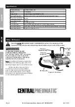
  Read the ENTIRE IMPORTANT SAFETY INFORMATION section at the beginning of this 

manual including all text under subheadings therein before set up or use of this product.

Compressor Area Set Up

1.  Designate a work area that is clean and well-lit.  

The work area must not allow access by 
children or pets to prevent injury.

2.  Locate the Compressor on a flat level surface to 

ensure proper pump lubrication and to prevent 

damage to the unit.  Keep at least 12″ of space 

around the unit to allow air circulation.

3.  Route the power cord from the compressor 

to the grounded wall outlet, along a safe path 
without creating a tripping hazard or exposing 
the power cord to possible damage.

General Operation

1.  Insert the Power Cord Plug (35) into the 

nearest 120 volt, grounded, electrical outlet.

2.  Connect an Air Brush (not included) to 

the Air Hose (43) of the Compressor.  
Use Hose Adapter (44) if needed.

Note:

  Use this Compressor only with air 

brushes; do not use this compressor with 
any other type of painting equipment.

3.  Turn the Power Switch (34) on.

Note: 

The Compressor will automatically begin 

to run when the air pressure falls below 

43 PSI

.  

When the maximum air pressure (

58 PSI

) is reached, 

the Compressor will automatically switch to 
idle and the Compressor will stop operating.  
The Compressor will automatically restart 
when the air pressure falls below 

43 PSI

.

4.  Adjust the regulated air pressure output as 

shown on the Pressure Gauge (11) by lifting 

the Regulator Knob (40), turning it to the 
desired pressure and pressing it back down.

5.  When finished using the Air Compressor, turn its 

Power Switch (34) off.  Release any remaining air 
in a safe fashion and disconnect the Air Brush.  
Briefly depress the Water Drain Valve (41) 
to empty the unit of water after each use.

6.  Store the Air Compressor in a clean, dry, 

safe location out of reach of children 
and other unauthorized people.

SAFETY

OPERA

TION

MAINTENANCE

SETUP

Summary of Contents for 93657

Page 1: ...l and the receipt in a safe and dry place for future reference Owner s Manual Safety Instructions Visit our website at http www harborfreight com Email our technical support at productsupport harborfr...

Page 2: ...ential personal injury hazards Obey all safety messages that follow this symbol to avoid possible injury or death Indicates a hazardous situation which if not avoided will result in death or serious i...

Page 3: ...ired or under the influence of drugs alcohol or medication A moment of inattention while operating a compressor may result in serious personal injury b Use personal protective equipment Always wear AN...

Page 4: ...you choose to use an extension cord use the following guidelines TABLE A RECOMMENDED MINIMUM WIRE GAUGE FOR EXTENSION CORDS 120 VOLT NAMEPLATE AMPERES at full load EXTENSION CORD LENGTH 25 50 100 150...

Page 5: ...of electric shock The conductor with insulation having an outer surface that is green with or without yellow stripes is the equipment grounding conductor If repair or replacement of the electric cord...

Page 6: ...manual including all text under subheadings therein before set up or use of this product TO PREVENT SERIOUS INJURY FROM ACCIDENTAL OPERATION Turn the Power Switch OFF and unplug the Air Compressor fr...

Page 7: ...sh not included to the Air Hose 43 of the Compressor Use Hose Adapter 44 if needed Note Use this Compressor only with air brushes do not use this compressor with any other type of painting equipment 3...

Page 8: ...rther use Cleaning Maintenance and Lubrication 1 BEFORE EACH USE inspect the general condition of the Air Compressor Check for loose hardware misalignment or binding of moving parts damaged belts crac...

Page 9: ...sary Not enough pressure when painting or spraying 1 Loose air connection s 2 Air hose is damaged 3 Screws on cylinder cover are loose 1 Check all air connections and tighten them if necessary 2 Repla...

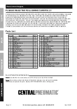
Page 10: ...MANUFACTURER AND OR DISTRIBUTOR HAS PROVIDED THE PARTS LIST AND ASSEMBLY DIAGRAM IN THIS MANUAL AS A REFERENCE TOOL ONLY NEITHER THE MANUFACTURER OR DISTRIBUTOR MAKES ANY REPRESENTATION OR WARRANTY O...

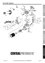
Page 11: ...Page 11 For technical questions please call 1 888 866 5797 Item 93657 Assembly Diagram 40 SAFETY OPERATION MAINTENANCE SETUP...

Page 12: ...amages so the above limitation of exclusion may not apply to you THIS WARRANTY IS EXPRESSLY IN LIEU OF ALL OTHER WARRANTIES EXPRESS OR IMPLIED INCLUDING THE WARRANTIES OF MERCHANTABILITY AND FITNESS T...

Reviews: