Page 10
For technical questions, please call 1-888-866-5797.
Item 93755
SA
FE
TY
OP
ERA
TI
O
N
MAINT
ENANC
E
SE
TUP
Assembly
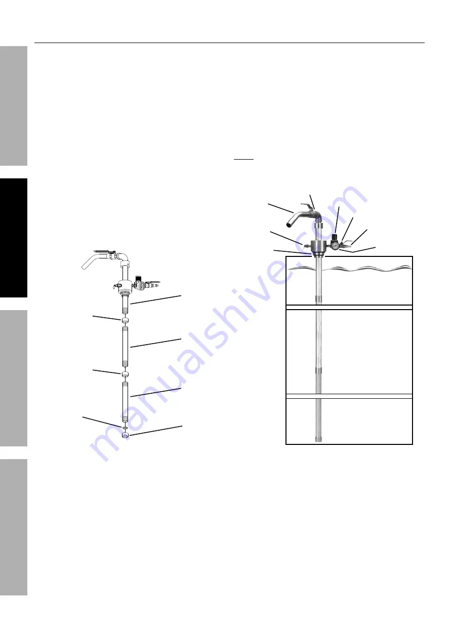
1. Wrap 4" of pipe sealer tape (not included) around
the male threads located on the lower section of
Suction Tube A (5). Then firmly screw a Suction
Tube Coupler (7) onto the Suction Tube.
2. Wrap 4" of pipe sealer tape around the male
threads on both ends of Suction Tube B (6). Then
firmly screw one end of Suction Tube B into the
Suction Tube Coupler attached to Suction Tube A.
3. Firmly screw the remaining Suction Tube Coupler
onto the lower section of Suction Tube B.
4. Wrap 4" of pipe sealer tape around the
male threads on both ends of the remaining
Suction Tube C (8). Then firmly screw one
end of Suction Tube C into the Suction Tube
Coupler attached to Suction Tube B.
5. Insert the Oil Filter (9) into the Inlet Plug (10).
Then, firmly screw the Inlet Plug onto the
lower section of Suction Tube C.
Inlet Plug
(10)
Oil Filter
(9)
Suction Tube
Coupler (7)
Suction
Tube A
(5)
Suction Tube
Coupler (7)
Suction
Tube B
(6)
Suction
Tube C
(8)
Figure C: Suction Tube Setup
6. Unscrew and remove the large bung from
the barrel of liquid to be extracted.
7. Insert the lower section of the Drum Extractor
through the bung of the barrel. Then
firmly screw the Drum Extractor into
the female threads of the bung.
8. To adjust the length of the tube in the
barrel, grasp the regulator assembly
and twist it up or down on the pipe.
Note:
The male threads of the Drum Extractor
are designed to fit a 1-1/2" or 2" diameter
bung. Refer to Figure D: Barrel Setup.
Barrel
(not included)
Outlet
Tube
Air Inlet Ball Valve
Regulator
Pressure
Gauge
Air Quick Coupler
Outlet Ball Valve
Pressure
Release
Valve
1-1/2"
~
2"
Diameter
Threads
Figure D: Barrel Setup


