background image

SKU 94734 

For technical questions, please call 1-800-444-3353.


Page 8

REV 07b

OPERATION

CAuTION! Prior to use, inspect the compressor for any damaged parts or unsafe con-

ditions.  Make any necessary repairs before using again.

Turning Compressor On

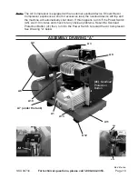
1.  Verify Tank Drain Valve (A-7) is closed.
2. 

Verify oil level is correct.

3.  Verify that the Safety Valve (A-4) is operational.
4.  Turn the Air Flow Valve (A-8) to the OFF position.
5.  Plug the power cord into an electrical grounded 115 Volt AC electrical receptacle.
6.  Rotate the  Power Switch (A-5) to the Vertical position to turn the air compressor on. 

Rotate that same switch to the horizontal position to turn it off.  See page 10. 

Note:   

Allow the pressure to build up to at least 80 PSI before using air. 

Note:

  Motor will not start if tank pressure is already between 80-115 PSI. Pressure 

MuST


be below 80 PSI for motor to restart and build up pressure to the 115 PSI cut off 

pressure.

7.  Open the Air Flow Valve (A-8) and check for air leaks. 
 

The operation of the compressor is automatic, as controlled by the internal pressure 

switch. When the pressure drops below its operating range the compressor turns on. 

When the pressure is above 115 PSI, the compressor shuts off.

Warning; The compressor will become very hot during operation. do not touch the 

cylinder area of the compressor, or allow flammable materials to come in contact with 

the cylinder area.

Adjusting Pressure gauge and Pressure Adjustment Screw

Caution: The Pressure Switch is adjustable but changes to the pressure levels are not 

recommended; any change to the automatic ON/OFF pressure levels will cause addi-

tional stress on the motor which may shorten motor life.

Adjusting Air Output

1.  When the Air Flow Valve (A-8) is to the right or left, the valve is closed.  When it is in 

the middle, it is open.

2.  Turn the Air Flow Valve to the appropriate pressure.

Summary of Contents for 94734

Page 1: ...s reserved No portion of this manual or any artwork con tained herein may be reproduced in any shape or form without the express written consent of Harbor Freight Tools Diagrams within this manual may...

Page 2: ...ures parts list and assembly diagram Keep your invoice with this manual Write the invoice number on the inside of the front cover Keep this manual and invoice in a safe and dry place for future refere...

Page 3: ...ld present a fire hazard Always unplug the air compressor and release the air pressure when not in use 5 PERSONAL SAFETY Stay alert Watch what you are doing and use common sense during use Do 1 not us...

Page 4: ...ssor serviced before using Many accidents are caused by poorly maintained compressors Use only accessories that are recommended by the manufacturer for your 7 model Accessories that may be suitable fo...

Page 5: ...afety Release Valve Do not attempt to readjust the automatic start and shutoff valves 8 Any change to the automatic ON OFF pressure levels will cause additional stress on the motor which may result in...

Page 6: ...ain lead a chemical known to the State of California to cause birth defects or other reproductive harm California Health Safety code 25249 5 et seq 21 WARNING The warnings precautions and instructions...

Page 7: ...ly designed for air compressors Never mix oils of different types Never use a low quality oil which may not afford adequate lubrication 4 Replace the Dipstick Install an Air Intake Filter and Hose not...

Page 8: ...UST be below 80 PSI for motor to restart and build up pressure to the 115 PSI cut off pressure 7 Open the Air Flow Valve A 8 and check for air leaks The operation of the compressor is automatic as con...

Page 9: ...r Grip 1 A 4 Safety Valve 1 A 5 ON OFF Switch 1 A 6 Air Tank 2 A 7 Tank Drain Valve 1 A 8 Air Flow Valve 1 A 9 One Way Valve 1 A 10 Air Tube 1 A 11 Base 1 A 12 Rubber Foot 1 A 13 Bolt and Nut 1 ea A 1...

Page 10: ...oad device will trip and the machine will automatically shut down If this happens turn Off the Power Switch A5 wait 10 minutes and check for any obvious problems Reset the Overload Protection Button 4...

Page 11: ...5 Compression Ring 1 B 16 Scraping Oil Ring 1 B 17 Piston 1 B 18 Piston Pin 1 B 19 Crankshaft Retainer 1 B 20 Dip Stick 1 B 21 Screw 1 Item Description Qty B 22 Connecting Rod 1 B 23 Crankshaft 1 B 24...

Page 12: ...e 12 Assembly Drawing B 41 34A 34B Note When ordering parts on this page add the prefix B to the part number Example B 1 is a Screw Note Some parts are listed and shown for illustration purposes only...

Page 13: ...SKU 94734 For technical questions please call 1 800 444 3353 Page 13 Troubleshooting Guide REV 07b...

Page 14: ...our facilities normal wear and tear or to lack of maintenance We shall in no event be liable for death injuries to persons or property or for incidental contingent special or consequential dam ages a...

Reviews: