Page 8
SKU 95370
for technical questions, please call 1-800-444-3353.
ASSEMbLy INSTRuCTIONS
wARNING! Make sure the Pressure Switch of the tool is in its “Off” position
and that the tool is unplugged from its electrical outlet, and all air pressure
is released before making any adjustments to the tool.
Mounting Handles and wheel
Note:
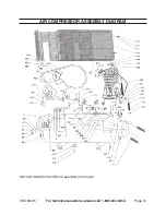
For additional information regarding the parts listed in the following pages, refer to
the Assembly Diagram near the end of this manual.
Mount each Handle (A15) to the end of each air Tank (A8) using two Bolts (A14).
Push on each Rubber Grip (A16) onto each Handle (A15).
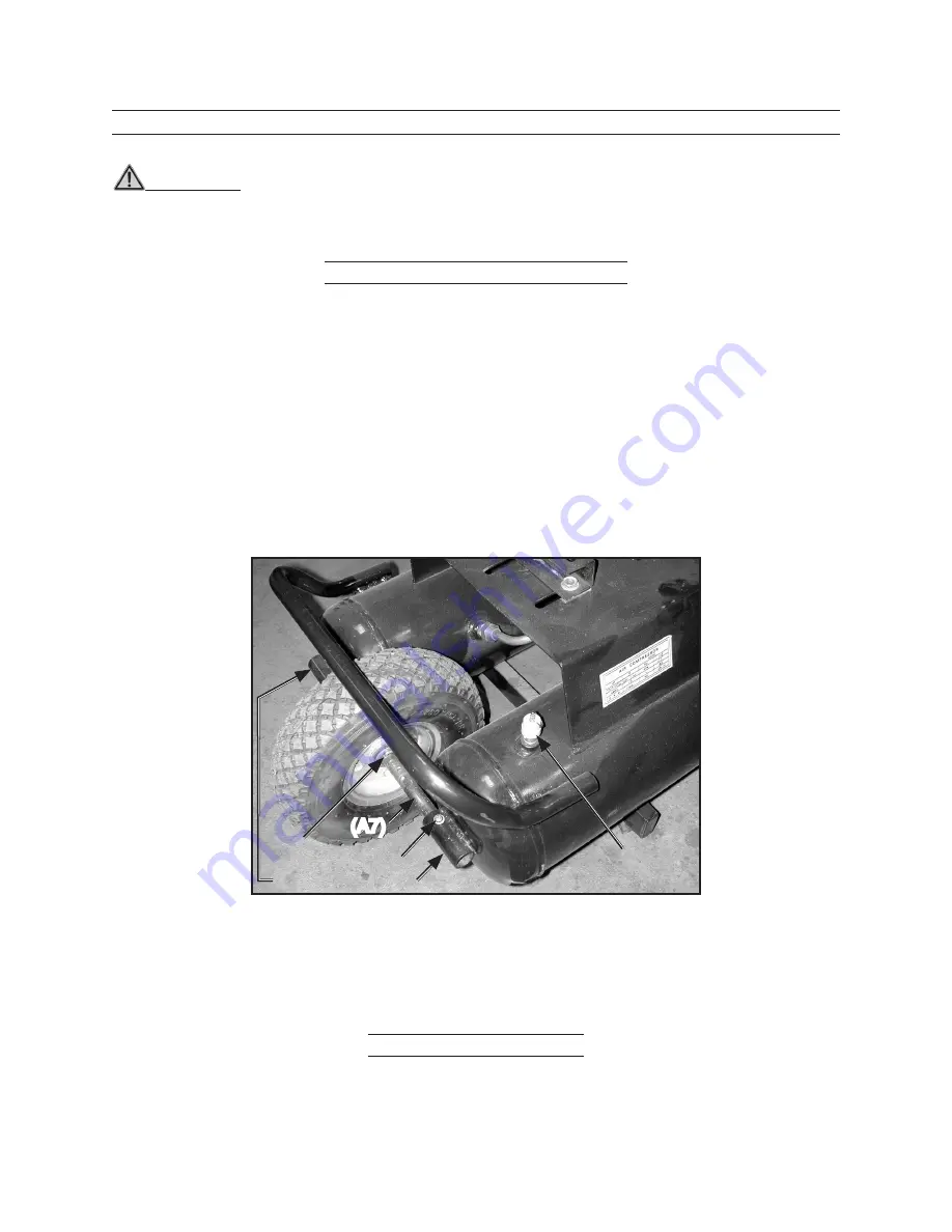
Place the Axle (A7) through the Tank Axle Mount, Gasket (A6), then through the
center of Wheel (A1).
On the other side of the Wheel, place another Gasket (A6) on the Axle, then slide
the Axle into the other Tank Axle Mount. See photo below.
Place Pins (A3) through holes in the Axle on each side of the Wheel and bend in
place so they do not fall out.
Align Axle mounting holes with the holes in the Tank Axle Mount. Screw in Bolts
(A4) with Lock Washer (A5) on each side of the Wheel.
Connecting Air Hose
Close the Tank Drain Valve (A13) under the Tank by turning it clockwise until it
stops.
1.
2.
3.
4.
5.
1.
(A4/A5)
Tank Axle Mount
(A3)
(A7)
Air Release
Safety Valve (A9)

