background image

Page 9

SKU 95370

for technical questions, please call 1-800-444-3353.

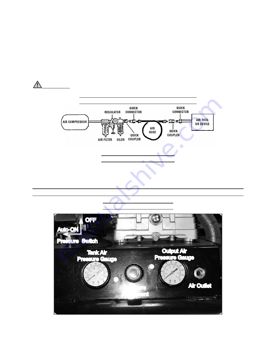
Connect the high pressure air hose to the Air Outlet (A27).  Refer to Controls and 
Indicators below. The outlet is 1/4” x 18 NPT.  For easy connection or removal, a 
quick coupler (not supplied) should be installed on the the air outlet.

To extend the life of most air tools, it is recommended to install an oiler and water 
filter in series with the air output line of the Air Compressor as shown below.

Connect the other end of the high pressure air hose to the air tool.

wARNING! : do not remove or try to adjust the factory sealed Pressure Switch 

(A29); removal can cause the Tank to over pressurize and explode.

Connect 220 V Line Plug

Purchase a 3-prong, twist-lock, 220 VAC line plug for the Air Compressor line cord. 

Have a qualified electrician connect the plug the line cord.

OPERATION INSTRuCTIONS

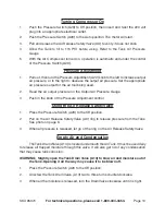
Controls and Indicators

2.

3.

4.

Output Air 

Pressure Gauge

Pressure  Switch

Tank Air 

Pressure Gauge

Pressure 

Adjustment

Air Outlet 

OFF

Auto-ON

Typical Air Compressor/Air Tool Set up

Summary of Contents for 95370

Page 1: ...1 Visit our website at http www harborfreight com To prevent serious injury read and understand all warnings and instructions before use Copyright 2006 by Harbor Freight Tools All rights reserved No p...

Page 2: ...assembly diagram Keep your invoice with this manual Write the invoice number on the inside of the front cover Write the product s serial number in the back of the manual near the assembly dia gram or...

Page 3: ...tions Water entering a power tool will increase the risk of electric shock Do not abuse the Power Cord Never use the Power Cord to carry the tools or pull the Plug from an outlet Keep the Power Cord a...

Page 4: ...stments changing accessories or storing the tool Such preventive safety measures reduce the risk of starting the tool accidentally Always unplug the tool from its electrical outlet before performing a...

Page 5: ...ays unplug the Air Compressor from its electrical outlet before performing any inspection maintenance or cleaning procedures or when not in use Before each use check all nuts bolts and screws for tigh...

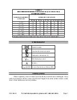
Page 6: ...inadequately sized wire causes a seri ous drop in voltage resulting in loss of power and possible tool damage See Table A The smaller the gauge number of the wire the greater the capacity of the cord...

Page 7: ...1 12 0 18 14 12 10 12 1 16 0 14 12 10 16 1 20 0 12 10 Based on limiting the line voltage drop to five volts at 150 of the rated amperes Symbology Double Insulated Canadian Standards Association Under...

Page 8: ...k A8 using two Bolts A14 Push on each Rubber Grip A16 onto each Handle A15 Place the Axle A7 through the Tank Axle Mount Gasket A6 then through the center of Wheel A1 On the other side of the Wheel pl...

Page 9: ...line of the Air Compressor as shown below Connect the other end of the high pressure air hose to the air tool WARNING Do not remove or try to adjust the factory sealed Pressure Switch A29 removal can...

Page 10: ...used Read the air output pressure on the Output Air Pressure Gauge Push in the knob of the Pressure Adjustment control Using the Air Release Safety Valve Press the Pressure Switch A29 to the Off posit...

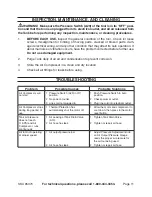
Page 11: ...r in a clean and dry location Check all air fittings for leaks before using Troubleshooting Problem Possible Causes Probable Solutions Air Compressor will not start Pressure Switch A29 in Off position...

Page 12: ...r consequential damages arising from the use of our product Some states do not allow the exclusion or limitation of incidental or consequential damages so the above limitation of exclusion may not app...

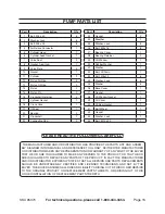
Page 13: ...Outlet 1 A28 Elbow 1 A29 Pressure Switch 1 A30 Power Cord 1 A31 Air Release Tube 1 A32 Nut 1 8 1 A33 O ring 1 A34 Connecting Pipe 1 Part Description Q ty A35 One way Valve 1 A36 Nut 3 4 2 A37 Radiato...

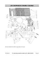
Page 14: ...Page 14 SKU 95370 For technical questions please call 1 800 444 3353 Air Compressor ASSEMBLY DIAGRAM A67 and A68 Start and Run Capacitors not shown...

Page 15: ...er 6 36 Base Cover 1 37 Gasket 1 38 Oil Window Gasket 1 39 Oil Cover 1 40 Oil Seal Gasket 1 41 Belt Wheel 1 42 Gasket 1 43 Washer Lock 1 44 Bolt M10 x 30 1 PLEASE READ THE FOLLOWING CAREFULLY The manu...

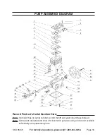
Page 16: ...353 Pump ASSEMBLY DIAGRAM Record Product s Serial Number Here Note If product has no serial number record month and year of purchase instead Note Some parts are listed and shown for illustration purpo...

Reviews: