background image

SKU 95386

For technical questions, please call 1-800-444-3353.

Page 13

PSI of the tool on the Output Pressure Gauge (60), push in the knob to set the
output pressure.  

(See Figure H.)

7.

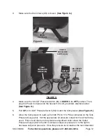
As long as the “On/Off” Pressure Switch (55) is in its 

ON

 position the operation of

the Compressor is automatic, controlled by an internal pressure switch.  The
Compressor will turn on automatically when the air pressure drops to 80 PSI as
indicated on the Pressure Gauge (54), and will turn off automatically when the air
pressure reaches 115 PSI as indicated.  

IMPORTANT:

 The internal pressure

switch is not user adjustable, 

never make changes to the air pressure levels.

Any change to the automatic pressure levels may cause excess pressure to
accumulate, causing a hazardous situation.

8.

NOTE:

  If it is necessary to quickly 

depressurize the Compressor, turn off the Air

Compressor by pushing 

DOWN

 on the “On/Off” Pressure Switch (55).  Then, pull

OUT

 on the ring on the Safety Valve (56) to quickly release stored air pressure.

9.

When finished using the Air Compressor, turn it off by pushing 

DOWN

 on the

”On/Off” Pressure Switch (55).  Unplug the Power Cord (64) from its electrical
outlet.  Squeeze the trigger on the air tool being used to release all stored air
pressure from the system, and disconnect the air hose and air tool from the Air
Compressor.  Then, open the Drain Valve (65) to release all remaining
compressed air from the  Tank (1).  Note: Accumulated mositure will also be
discharged.  

(See Figure G.)

10.

NOTE:

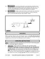
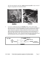
  The Compressor is equipped with a Reset Button (19).  (

See Figure I

.)

Should the Compressor overheat while in use, the machine will automatically
shut down.  If this happens, push 

DOWN 

on the “On/Off” Pressure Switch (55).

Wait for the unit to cool off (usually 5-10 minutes).  Then, press the Reset Button
(19) and pull 

UP

 on the “On/Off” Pressure Switch (55) to restart the Compressor. If

overheating is a reoccurring problem, make certain that the extension cord used
is of the proper gauge and length for this unit’s power requirements - as explained
on page 7.

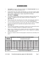
Figure I

RESET

BUTTON (19)

Summary of Contents for 95386

Page 1: ...p www harborfreight com Copyright 2006 by Harbor Freight Tools All rights reserved No portion of this manual or any artwork contained herein may be reproduced in any shape or form without the express...

Page 2: ...THESE INSTRUCTIONS WORK AREA 1 Keep your work area clean and well lit Cluttered benches and dark areas invite accidents m e t I n o i t p i r c s e D s t n e m e r i u q e R l a c i r t c e l E M P R...

Page 3: ...es not fit contact a qualified electrician to install a polarized outlet Do not change the plug in any way Double insulation eliminates the need for the three wire grounded power cord and grounded pow...

Page 4: ...SI approved eye and ear protection Dust mask non skid safety shoes hard hat or hearing protection must be used for appropriate conditions TOOL USE AND CARE 15 Do not force the tool Use the correct too...

Page 5: ...g the grounding wire can result in the risk of electric shock Check with a qualified electrician if you are in doubt as to whether the outlet is properly grounded Do not modify the power cord plug pro...

Page 6: ...TOOLS TOOLS WITH TWO PRONG PLUGS 4 Tools marked Double Insulated do not require grounding They have a special double insulation system which satisfies OSHA requirements and complies with the applicabl...

Page 7: ...e sum to determine the required minimum cord size See Figure C 6 If you are using an extension cord outdoors make sure it is marked with the suffix W A W in Canada to indicate it is acceptable for out...

Page 8: ...oved safety impact eye goggles and hearing protectors when using this product 4 Do not allow children to use or play with this product 5 Store idle equipment When not in use tools and equipment should...

Page 9: ...l operate properly and perform its intended function Check for damaged parts and any other conditions that may affect the operation of this product Replace or repair damaged or worn parts immediately...

Page 10: ...is below the red circle carefully unscrew and remove the Oil Plug 31 and UNPACKING When unpacking check to make sure all the parts shown on the Parts Lists on page 15 are included If any parts are mis...

Page 11: ...luded equipped with a quick connector not included to the Air Outlet Valve If using a water filter and oiler in series with the Air Outlet Valve of the Air Compressor connect the other end of the air...

Page 12: ...ressor See Figure H 6 Allow the Compressor to build up from 80 PSI to 115 PSI as indicated on the Tank Pressure Gauge 54 Set the appropriate air pressure output for the air tool being used Pull out an...

Page 13: ...on the ring on the Safety Valve 56 to quickly release stored air pressure 9 When finished using the Air Compressor turn it off by pushing DOWN on the On Off Pressure Switch 55 Unplug the Power Cord 64...

Page 14: ...y the merchandise If our inspection veri es the defect we will either repair or replace the product at our election or we may elect to refund the purchase price if we cannot readily and quickly provid...

Page 15: ...an 47 Cylinder gasket 14 Black motor cover 48 Valve plate assembly 15 Wave washer 49 Limit pin 16 Bearing 6202 RZ 50 Air intake valve 17 Screw M5x105 51 Piston pin 18 Stator 52 Circlip 19 Reset button...

Page 16: ...CT OR THAT HE OR SHE IS QUALIFIED TO REPLACE ANY PARTS OF THE PRODUCT IN FACT THE MANUFACTURER AND OR DISTRIBUTOR EXPRESSLY STATES THAT ALL REPAIRS AND PARTS REPLACEMENTS SHOULD BE UNDERTAKEN BY CERTI...

Reviews: