background image

SKU 95498 

For technical questions, please call 1-800-444-3353. 

Page 12

INSPECTION, MAINTENANCE, ANd CLEANING

  Procedures not specifically explained in this manual must be performed 

only by a qualified technician.


TO PREVENT SERIOuS INjuRY FROM ACCIdENTAL 

OPERATION: 

Turn the Power Switch of the tool to its “OFF” position and unplug the 

tool from its electrical outlet before performing any inspection, 

maintenance, or cleaning procedures.

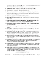
Before each use,

1. 

 inspect the general condition of the Air Compressor.  Check for 

loose screws, misalignment or binding of moving parts, cracked or broken parts, 

damaged electrical wiring, loose air fittings, and any other condition that may affect 

the safe operation of the Compressor.  If abnormal noise or vibration occurs, have 

the problem corrected before further use.  

do not use damaged equipment.

Before each use, 

2. 

check the compressor oil level in the Oil Sight Glass (22).  If 

necessary, fill the crankcase of the Air Compressor with the proper amount and 

type of compressor oil.

daily, 

3. 

purge the Air Tanks (51) of all air and moisture to prevent corrosion.  To do 

so, slowly and carefully unscrew (no more than four threads) the Tank Drain Valve 

(52) until the compressed air and condensation begins to be released from the 

Tanks.  Allow sufficient time for all of the air and condensation to escape from the 

Tanks.  Then, firmly re-tighten the Drain Valve.

TROuBLESHOOTING

Problem

Possible Cause

Possible Solution

Compressor will not 

start.

Blown fuse or circuit 

1. 

breaker tripped.
Loose electrical 

2. 

connections.
Bad capacitors.

3. 

Replace or reset fuse/circuit breaker. 

1. 

Plug Compressor into a working, 120 volt, 

2. 

grounded, electrical outlet.
Replace capacitors.

3. 

Low pressure.

Restricted air filter.

1. 

Defective check valve. 

2. 

Air leak in safety valve. 

3. 


Defective valve plate.

4. 

Replace air filter.

1. 

Have a qualified service technician replace 

2. 

check valve.
Check valve by pulling on ring.  If condition 

3. 

persists, have a qualified service technician 

replace valve.
Replace valve plate.

4. 

Safety valve releasing.

Defective pressure 

1. 

switch.
Defective safety valve.

2. 

Have a qualified service technician replace 

1. 

pressure switch.
Replace safety valve.

2. 

Summary of Contents for 95498

Page 1: ...http www harborfreight com Read this material before using this product Failure to do so can result in serious injury Save this manual Copyright 2007 by Harbor Freight Tools All rights reserved No por...

Page 2: ...S AND PRECAUTIONS WARNING READ AND UNDERSTAND ALL INSTRUCTIONS Failure to follow all instructions listed below may result in electric shock fire and or serious injury SAVE THESE INSTRUCTIONS WORK AREA...

Page 3: ...Do not force the tool Use the correct tool for your application 1 The correct tool will do the job better and safer at the rate for which it is designed Do not use the Compressor if the Compressor s P...

Page 4: ...ent is necessary to properly filter and purify the air to meet minimal specifications for Grade D breathing as described in Compressed Gas Association Commodity Specification G 7 1 1966 OSHA 29 CFR 19...

Page 5: ...tool will do the work better and safer at the speed and capacity for which it was designed Avoid body contact with oils and lubricants used in the Compressor 17 If swal lowed seek medical treatment im...

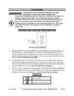
Page 6: ...three prong 1 grounding plug The plug must be connected to a properly grounded outlet If the tool should electrically malfunction or break down grounding provides a low resistance path to carry elect...

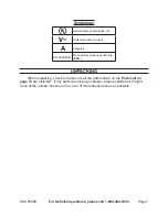
Page 7: ...lternating Current A Amperes n0 xxxx min No Load Revolutions per Minute RPM UNPACKING When unpacking check to make sure all the parts shown on the Parts List on page 13 are included If any parts are m...

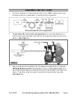
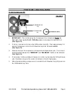
Page 8: ...oiler and water filter in line with the Air Outlet Valve 68 of the Air Com pressor See Figure C QUICK CONNECTOR NOT INCLUDED AIR OUTLET VALVE 68 FIGURE D WRAP WITH PIPE SEALANT TAPE NOT INCLUDED HERE...

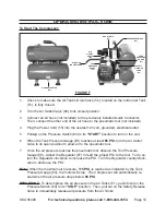
Page 9: ...e the Oil Breather Cap 25 Pour approximately 1 2 quart of compressor oil into the Oil Breather Cap hole Do not overfill See Figure E Observe the level of compressor oil through the Oil Sight Glass 22...

Page 10: ...up on the Pressure Switch 64 to its START position to turn on the unit When the Tank Pressure Gauge 63 reaches at least 6 85 PSI turn the Air Outlet Valve to its open position to allow air to the pneu...

Page 11: ...m the tool and store the tool in a clean dry safe location out of reach of children Disconnect the other end of the air hose from the Compressor s Air Outlet Valve 5 68 and store the air hose in a cle...

Page 12: ...and type of compressor oil Daily 3 purge the Air Tanks 51 of all air and moisture to prevent corrosion To do so slowly and carefully unscrew no more than four threads the Tank Drain Valve 52 until the...

Page 13: ...ability arising out of his or her repairs to the original product or replacement parts thereto or arising out of his or her installation of replacement parts thereto PARTS LIST Part Description 1 Plas...

Page 14: ...call 1 800 444 3353 Page 14 ASSEMBLY DIAGRAM REV 08k 1 55 53 54 52 51 61 50 49 56 79 48 26 27 28 29 30 31 32 33 34 35 36 37 38 39 40 41 42 43 44 45 46 47 68 67 66 65 62 64 63 2 3 4 5 6 7 8 9 10 11 13...

Page 15: ...ecial or consequential damages arising from the use of our product Some states do not allow the exclusion or limitation of incidental or consequential damages so the above limita tion of exclusion may...

Reviews: