SKU 95498
For technical questions, please call 1-800-444-3353.
Page 8
ASSEMBLY INSTRuCTIONS
Turn the Compressor’s Pressure Switch (64) is in its
1.
“OFF”
position prior to per-
forming any service, maintenance, or cleaning of the Compressor.
2.
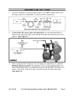
To extend the life of your tools and equipment,
it is recommended that you
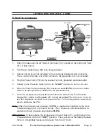
install an oiler and water filter in-line with the Air Outlet Valve (68) of the Air Com
-
pressor.
(See Figure C.)
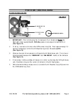
QuICK CONNECTOR
(NOT INCLudEd)
AIR OuTLET VALVE
(68)
FIGuRE d
WRAP
WITH
PIPE SEALANT TAPE
(NOT INCLudEd)
HERE
3. Prior to using the Air Compressor, the unit requires the attachment of a
1/4”-18
NPT Male Quick Connector
(not included). To do so, wrap approximately 3” of
pipe thread sealant tape (not included) around the male threads of the Quick Con-
nector. Then firmly screw the Quick Connector into the Air Outlet Valve (68).
(See Figure d.)

