background image

PLEASE READ THE FOLLOWING CAREFULLY

THE MANUFACTURER AND/OR DISTRIBUTOR HAS PROVIDED THE PARTS LIST AND ASSEMBLY
DIAGRAM IN THIS MANUAL AS A REFERENCE TOOL ONLY.  NEITHER THE MANUFACTURER OR
DISTRIBUTOR MAKES ANY REPRESENTATION OR WARRANTY OF ANY KIND TO THE BUYER THAT
HE OR SHE IS QUALIFIED TO MAKE ANY REPAIRS TO THE PRODUCT, OR THAT HE OR SHE IS
QUALIFIED TO REPLACE ANY PARTS OF THE PRODUCT.  IN FACT, THE MANUFACTUER AND/OR
DISTRIBUTOR EXPRESSLY STATES THAT ALL REPAIRS AND PARTS REPLACEMENTS SHOULD BE
UNDERTAKEN BY CERTIFIED AND LICENSED TECHNICIANS, AND NOT BY THE BUYER.  THE BUYER
ASSUMES ALL RISK AND LIABILITY ARISING OUT OF HIS OR HER REPAIRS TO THE ORIGINAL
PRODUCT OR REPLACEMENT PARTS THERETO, OR ARISING OUT OF HIS OR HER INSTALLATION
OF REPLACEMENT PARTS THERETO.

SKU 09592

PAGE 9

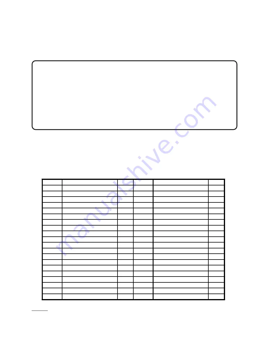
PARTS LIST

Part #

Description

Qty.

Part #

Description

Qty.

1

Screw

6

21

Bolt

3

2

Cylinder Head

1

22

Crankcase Front Cover

1

3

Exhaust Elbow

1

23

Crankcase Front Washer

1

4

Air Filter

1

24

O-Ring

1

5

Spring Washer

2

25

Oil Window

1

6

Screw

2

26

Oil Drain Plug

1

7

Cylinder Head Washer

1

27

O-Ring

1

8

Valve Plate Seat

2

28

Crankcase Seal

1

9

Valve Plate

4

29

Crankcase Down Cover

1

10

Aluminum Washer

1

30

Bolt

8

11

Cylinder Up Washer

2

31

Crankcase

1

12

Piston Ring Assembly

2

32

Bearing

2

13

Piston

2

33

Crankshaft

1

14

Piston Pin

2

34

Crankcase Back Washer

1

15

Retaining Ring In Hole

4

35

Oil Seal

1

16

Connect Rod Assembly

2

36

Crankcase Back Cover

1

17

Bolt

6

37

Bolt

3

18

Cylinder

1

38

Pulley

1

19

Cylinder Down Washer

1

39

Large Washer

1

20

Oil Fill Plug

1

40

Bolt

1

NOTE: Some parts are listed and shown for illustration purposes only, and are not
available individually as replacement parts.

Summary of Contents for 9592

Page 1: ...011 Visit our Web site at http www harborfreight com Copyright 2003 by Harbor Freight Tools All rights reserved No portion of this manual or any artwork contained herein may be reproduced in any shape...

Page 2: ...ry location to inhibit rust Always lock up tools and equipment and keep out of reach of children 4 DO NOT USE THIS PRODUCT IF UNDER THE INFLUENCE OF ALCOHOL OR DRUGS Read warning labels on prescriptio...

Page 3: ...affect the operation of this product Re place or repair damaged or worn parts immediately 11 REPLACEMENT PARTS AND ACCESSORIES When servicing use only identical replacement parts Only use accessories...

Page 4: ...structions grease oil trash and other debris Do not use the Air Compressor Pump in areas near flammable chemicals dusts and vapors 6 AVOID INJURY Never direct the Exhaust Elbow part 3 at people or ani...

Page 5: ...accessories 3 At the base of the Air Compressor Pump are four 3 8 mounting holes with a hole pattern of 5 1 2 long by 7 1 2 wide If four 3 8 mounting holes with a hole pattern of 5 1 2 long by 7 1 2...

Page 6: ...3 HP Motor s Pulley not included Once the V Belt Pulley is installed its proper length is indicated by pushing down with your finger midway on the V Belt Pulley The V Belt Pulley should not de press m...

Page 7: ...sure to wrap the male threads of Tank s Inlet Hose Connector with pipe seal tape not included Then screw the Con nector firmly into the Exhaust Elbow See Figure D EXHAUST ELBOW 3 AIR FILTER 4 OIL FILL...

Page 8: ...rther use Do not use damaged equipment 3 DAILY Check the Air Compressor Pump s oil level If necessary fill with a pre mium quality 30 weight non detergent oil NOTE When checking the oil level make sur...

Page 9: ...N OF REPLACEMENT PARTSTHERETO SKU 09592 PAGE 9 PARTS LIST Part Description Qty Part Description Qty 1 Screw 6 21 Bolt 3 2 Cylinder Head 1 22 Crankcase Front Cover 1 3 Exhaust Elbow 1 23 Crankcase Fron...

Page 10: ...r illustration purposes only and are not available individually as replacement parts SKU 09592 PAGE 10 ASSEMBLY DIAGRAM 30 29 28 27 26 25 24 23 22 21 20 19 18 17 16 20 31 32 33 34 35 32 36 37 38 39 40...

Reviews: