background image

Page 11

SKU 96496

For technical questions, please call 1-800-444-3353.

Switch to its “OFF” position.  Wait until the Motor cools.  Press the Overload 

Protector (3) button.  Then restart the Air Compressor.
To stop the Air Compressor, turn the Power Switch (2) to its 

“OFF”

 position.  

Then unplug the Compressor from its electrical outlet.  

(See Figure b)

Pull the Safety Valve (20) to release any remaining air pressure from the Air Tank 

(29).  Next, squeeze the trigger on the pneumatic tool to release any remaining 

air pressure from the tool.  Then, disconnect the air hose from the Air Outlet 

Valve (26).  

(See Figure b)

Remove any moisture from the Air Tank (29) by opening the Drain Valve (33).  

Then, retighten the Drain Valve.  

(See Figure b)

Allow the Air Compressor to completely cool.  Then store the Compressor in a 

clean, dry, safe location out of reach of children and other unauthorized people. 

10.

11.

12.

13.

MAINtENANCE ANd SERVICING

Risk of serious personal injury from accidental starting 

or electric shock.  turn the Power Switch of the tool to its 

“OFF” position and unplug the tool from its electrical outlet 

before performing any inspection, maintenance, or cleaning 

procedures.
damaged equipment can fail, causing serious personal 

injury.  do not use damaged equipment.  If abnormal noise or 

vibration occurs, have the problem corrected before further 

use.

Inspection, Maintenance, And Cleaning

bEFORE EACH uSE,

 inspect the general condition of the Air Compressor.  

Check for loose screws, misalignment or binding of moving parts, cracked or 

broken parts, damaged electrical wiring, and any other condition that may affect 

its safe operation.

AFtER EACH uSE, 

remove any moisture from the Air Tank (29) by opening the 

Drain Valve (33).  Then, retighten the Drain Valve.  

(See Figure b) 

AFtER EACH uSE,

 clean the external surfaces of the Air Compressor with a 

clean, moist cloth.  Then dry.  Do not use solvents.  Do not introduce water into 

the electrical components of the Air Compressor.

WARNING!  

if the supply cord of this power tool is damaged, it must be replaced 

only by a qualified service technician.

CAutION!  

All maintenance, service, and repairs not mentioned in this manual 

must only be performed by a qualified service technician.

1.

2.

3.

4.

.

WARNING

WARNING

Summary of Contents for 96469

Page 1: ...te at http www harborfreight com Read this material before using this product Failure to do so can result in serious injury Save this manual Copyright 2007 by Harbor Freight Tools All rights reserved...

Page 2: ...the safety alert symbol It is used to alert you to potential personal injury hazards Obey all safety messages that follow this symbol to avoid possible injury or death DANGER indicates a hazardous sit...

Page 3: ...urfaces such as pipes radiators ranges and refrigerators There is an increased risk of electric shock if your body is earthed or grounded Do not expose power tools to rain or wet conditions Water ente...

Page 4: ...safety measures reduce the risk of starting the power tool accidentally Store idle power tools out of the reach of children and do not allow people unfamiliar with the power tool or these instructions...

Page 5: ...g in damage from rupture or explosion Always replace worn cracked or damaged Tanks WARNING Never use plastic PVC pipe for compressed air serious injury or death could result Any tube pipe or hose used...

Page 6: ...h Safety code 25249 5 et seq WARNING The warnings and precautions discussed in this manual cannot cover all possible conditions and situations that may occur It must be understood by the operator that...

Page 7: ...all codes and ordinances The plug and outlet should look like those in the following illustration See 3 Prong Plug and Outlet Double Insulated Tools Tools with Two Prong Plugs Tools marked Double Insu...

Page 8: ...Up to Handle Net Weight 86 Pounds Unpacking When unpacking check to make sure that the item is intact and undamaged If any parts are missing or broken please call Harbor Freight Tools at the number s...

Page 9: ...tlet Valve 26 of the Air Compressor See Figure A FIGURE A PRODUCT FEATURES Operating Instructions Read the entire Important Safety Information section at the beginning of this manual including all tex...

Page 10: ...Turn the Power Switch 4 to its ON position to start the unit See Figure B When the Tank Air Pressure Gauge 35 reaches at least 125 PSI turn the air Pressure Controller 12 clockwise or counterclockwise...

Page 11: ...of the tool to its OFF position and unplug the tool from its electrical outlet before performing any inspection maintenance or cleaning procedures Damaged equipment can fail causing serious personal i...

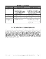
Page 12: ...r Switch not operating properly Damaged Power Switch 1 Immediately disconnect Power Cord from its electrical outlet Do not use Compressor until a qualified service technician repairs Power Switch 1 PL...

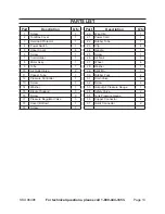
Page 13: ...2 Pressure Controller 1 13 Screw 1 14 Washer 1 15 Bracket Support 3 16 Screw 3 17 Pressure Regulator Valve 3 18 Cover Bottom 1 19 Screw 1 Part Description Q ty 20 Wire Clip 1 21 Power Cord 1 22 Rubber...

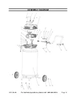
Page 14: ...Page 14 SKU 96496 For technical questions please call 1 800 444 3353 ASSEMBLY DIAGRAM...

Page 15: ...of maintenance We shall in no event be liable for death injuries to persons or property or for incidental contingent special or consequential damages arising from the use of our product Some states d...

Reviews: