background image

Page 11

SKU 97080

For technical questions, please call 1-800-444-3353.

Problem

Possible Cause

Possible Solution

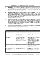
Compressor will not start.

Blown fuse or circuit breaker 

1. 

tripped.

Loose electrical 

2. 

connections.

Bad Capacitors.

3. 

Replace fuse.

1. 

Make sure Compressor is plugged 

2. 

into a working, 120 volt, grounded, 
electrical outlet.

Replace Capacitors.

3. 

Low pressure.

Defective check valve.

1. 

Air leak in safety valve.

2. 

Defective Valve Plate.

3. 

Drain Valve not fully closed.

4. 

Have a qualified service technician 

1. 

replace check valve.

Check valve by pulling on ring.  If 

2. 

condition persists, have a qualified 

service technician replace valve.

Replace Valve Plate.

3. 

Close Drain Valve.

4. 

Safety valve releasing.

Defective pressure switch.

1. 

Defective Safety Valve

2. 

.

Have a qualified service technician 

1. 

replace pressure switch.

Replace Safety Valve.

2. 

Pressure switch will not turn 
off Compressor.

Defective pressure switch.

Immediately unplug Compressor from 
its electrical outlet.  Do not operate 

Compressor until a qualified service 

technician can replace pressure 
switch.

before each use,

2. 

 inspect the general condition of the Air Compressor.  Check for 

loose screws, misalignment or binding of moving parts, cracked or broken parts, 

damaged electrical wiring, loose air fittings, and any other condition that may affect 

the safe operation of the Compressor.  If abnormal noise or vibration occurs, have 
the problem corrected before further use. 
Do not use damaged equipment.

Daily, purge the Air Tank (53) of all air and moisture to prevent corrosion.  To do so, 

3. 

slowly and carefully unscrew (no more than four threads) the Tank Drain Valve (54) 
until the compressed air and condensation begins to be released from the Tanks.  

Allow sufficient time for all of the air and condensation to escape from the Tanks.  

Then, firmly re-tighten the Drain Valve.

CAUTION!  All maintenance, service, or repairs not mentioned in this manual must 

4. 

only be performed by a qualified service technician.

To replace the Fuse (43), unscrew the fuse and replace with a 250V, 3A fuse.

5. 

tROubLEShOOtING

INSPECtION, MAINtENANCE, ANd CLEANING

WARNING!

1. 


Make sure the ON/OFF Power Switch (45) of the Air Compressor 

is in its “STOP” position, the unit is unplugged from its electrical outlet, and air is 
drained  from  the  Tank  (53)  before  performing  any  inspection,  maintenance,  or 
cleaning procedures or leaving it unattended.


Summary of Contents for 97080

Page 1: ...hts reserved No portion of this manual or any artwork contained herein may be reproduced in any shape or form without the express written consent of Harbor Freight Tools Diagrams within this manual ma...

Page 2: ...Write the invoice number on the inside of the front cover Keep this manual and invoice in a safe and dry place for future reference GENERAL SAFETY RULES AND PRECAUTIONS WARNING READ AND UNDERSTAND ALL...

Page 3: ...bles better control of the air tool in unexpected situations Use safety equipment Always wear ANSI approved safety impact 6 glasses dust mask respirator and hearing protection during use TOOL USE AND...

Page 4: ...D breathing as described in Compressed Gas Association Commodity Specification G 7 1 1966 OSHA 29 CFR 1910 134 and or Canadian Standards Associations CSA In the event the Air Compressor is used for th...

Page 5: ...authorized people to handle or play with the Air 15 Compressor Do not modify the factory set pressure shutoff or startup switches This tool will do 16 the work better and safer at the speed and capaci...

Page 6: ...ave a three wire cord and three prong grounding plug The plug must be connected to a properly grounded outlet If the tool should electrically malfunction or break down grounding provides a low resista...

Page 7: ...ing or broken please call Harbor Freight Tools at the number shown on the cover of this manual as soon as possible ASSEMBLY INSTRUCTIONS CAUTION 1 Always make sure the Compressor s Power Switch 45 is...

Page 8: ...in line shutoff valve is an important safety device because it controls the air supply even if the air hose is ruptured Note If an automatic oiler system is not used add a few drops of Pneumatic Tool...

Page 9: ...closed Pull on the Safety Valve 25 to verify that it is not stuck See Figures B and C Plug the Power Cord 35 into the nearest 120 volt grounded electrical outlet 2 Push in the ON side of the ON OFF Po...

Page 10: ...OTE When the maximum air pressure 100 PSI is reached as indicated by the Tank Pressure Gauge 26 the motor will stop The Compressor will automatically restart when the air pressure drops below 85 PSI S...

Page 11: ...inspect the general condition of the Air Compressor Check for loose screws misalignment or binding of moving parts cracked or broken parts damaged electrical wiring loose air fittings and any other c...

Page 12: ...gulator 1 25 Safety Valve 1 26 Tank Pressure Gauge 1 27 Two Way Valve 1 29 Muffler Board 1 30 Screw M3 x 6 4 31 Copper Connector Rod 2 32 Copper Hoop 2 33 Screw M6 x 25 4 Part Description Qty 34 Dampi...

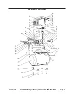
Page 13: ...Page 13 SKU 97080 For technical questions please call 1 800 444 3353 ASSEMBLY DIAGRAM 70 26...

Page 14: ...purchase date and an explanation of the complaint must accompany the merchandise If our inspection verifies the defect we will either repair or replace the product at our election or we may elect to...

Reviews: