background image

SKU 98635 

For technical questions, please call 1-800-444-3353. 

Page 11

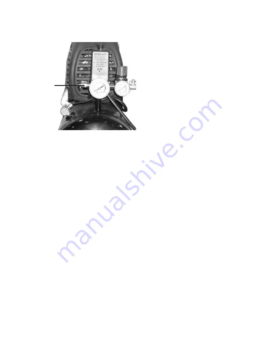
FIGuRE F

SAFEtY VALVE

(59)

10. 

When finished using the Compressor, 

push down on the Power Switch (60) 

to its “STOP” position.   

(See Figures E and F.)

Unplug the Power Cord (67) from its 

11. 

electrical outlet.
Remove any moisture in the Com-

12. 

pressor’s Tank (1) by opening the 

Drain Valve (53) (no more than two 

turns).  Then, retighten the Drain 

Valve.  

(See Figure C.)

Squeeze the trigger on the pneumatic 

13. 

tool to release any remaining air pres-

sure from the tool.  Then disconnect 

the air hose from the tool, and store 

the tool in a clean, dry, safe location 

out of reach of children.
Disconnect the other end of the air 

14. 

hose from the Quick Coupling (63) 

on the Compressor and store the air 

hose in a clean, dry, safe location out 

of reach of children.
Allow the Compressor to completely 

15. 

cool.  Then store the unit in a clean, 

dry, safe location out of reach of chil-

dren.

Summary of Contents for 98635

Page 1: ...served No portion of this manual or any artwork contained herein may be reproduced in any shape or form without the express written consent of Harbor Freight Tools Diagrams within this manual may not...

Page 2: ...us situation which if not avoided could result in minor or moderate injury NOTICE is used to address practices not related to personal injury CAUTION without the safety alert symbol is used to address...

Page 3: ...off po sition before connecting to power source picking up or carrying the tool Carrying power tools with your finger on the switch or energizing power tools that have the switch on invites accidents...

Page 4: ...to an electrical outlet Turn off the Com pressor and unplug it from its electri cal outlet before leaving This product is not a toy Keep it out 4 of reach of children People with pacemakers should 5 c...

Page 5: ...d result Any tube pipe or hose used must have a pressure rating higher than 150 PSI Minimum recommended pipe size Up to 50 feet long use 1 2 diameter Greater than 50 feet use 3 4 diam eter Larger diam...

Page 6: ...d have a three wire cord and three prong grounding plug The plug must be connected to a properly grounded outlet If the tool should electrically malfunction or break down grounding provides a low resi...

Page 7: ...PSI Crankcase Oil Type SAE30 or L DAB 100 over 50 F SAE10 or L DAB 68 under 50 F Oil Capacity 8 5 ounces Unpacking When unpacking check to make sure that the item is intact and undamaged If any parts...

Page 8: ...ee Figure B Tool Air Compressor Quick Coupler Air Hose on Reel Filter Regulator with Pressure Gauge Male Connector Male Connector Valve Quick Coupler Attach an air hose to the Compres 7 sor s Quick Co...

Page 9: ...procedures Work Piece and Work Area Set Up Designate a work area that is clean 1 and well lit The work area must not allow access by children or pets to prevent injury and distraction Route the Power...

Page 10: ...aches the pneu 7 matic tool observe the Tool Pressure Gauge 64 Adjust the Regulator 62 to feed the proper PSI to the tool To do so turn the Regulator clockwise to increase PSI to the tool Turn the Reg...

Page 11: ...n two turns Then retighten the Drain Valve See Figure C Squeeze the trigger on the pneumatic 13 tool to release any remaining air pres sure from the tool Then disconnect the air hose from the tool and...

Page 12: ...Carefully unscrew no more than two turns the Drain Valve 53 until the compressed air and moisture begins to be discharged from the Tank Allow sufficient time for all of the air and moisture to escape...

Page 13: ...SKU 98635 For technical questions please call 1 800 444 3353 Page 13 Power switch will not turn off Compressor 1 Defective power switch power switch...

Page 14: ...sher 5 47 Connecting Rod 14 Motor Stator 48 Capacitor 15 Motor Rotor 49 Wheel Assembly 16 Bearing 6203 50 Wheel Shaft Screw 17 Oil Seal 51 Wheel Shaft Sleeve 18 Crankcase 52 Hex Nut M8 19 Crank 53 Dra...

Page 15: ...SKU 98635 For technical questions please call 1 800 444 3353 Page 15 ASSEMBLY DIAGRAM...

Page 16: ...of incidental or consequential damages so the above limita tion of exclusion may not apply to you This warranty is expressly in lieu of all other warranties express or implied including the warranties...

Reviews: