background image

SKU 99640 

For technical questions, please call 1-800-444-3353. 

Page 7

SPECIFICATIONS

Air Pressure 

Range

70-120 PSI

Maximum Air 

Pressure

120 PSI

Air Inlet

1/4” -18 NPT

Fastener 

Capacity and 

Size Range

120 1/2” Crown Flooring Staples 

Length: 1-1/2” to 2” 

Gauge: 15 1/2 Ga 

100 “L” or “T” Type Flooring Cleats 

Length: 1-1/2” to 2” 

Gauge: 16 Ga

Air 

Consumption

4 SCFM @ 90 PSI

Safety Trigger Slugging Actuation Only 

(No Safety)

Accessories

Wrench Set 

Slugging Hammer 

Air Coupler Adapter 

Air Tool Oil Dropper 

Spare Base Plate

UNPACKING

When unpacking, check to make sure 

that the item is intact and undamaged.  If 

any parts are missing or broken, please 

call Harbor Freight Tools at the number 

shown throughout the manual as soon as 

possible.

• This air tool may be shipped with a 

protective plug covering the air inlet.  

Remove this plug before set up.

ASSEMBLY

  Read the ENTIRE IMPORTANT 

SAFETY INFORMATION 

section at the beginning of this 

manual including all text under 

subheadings therein before set 

up or use of this product.

Note:

  For additional information regarding 

the parts listed in the following pages, 

refer to the Assembly Diagram near 

the end of this manual.
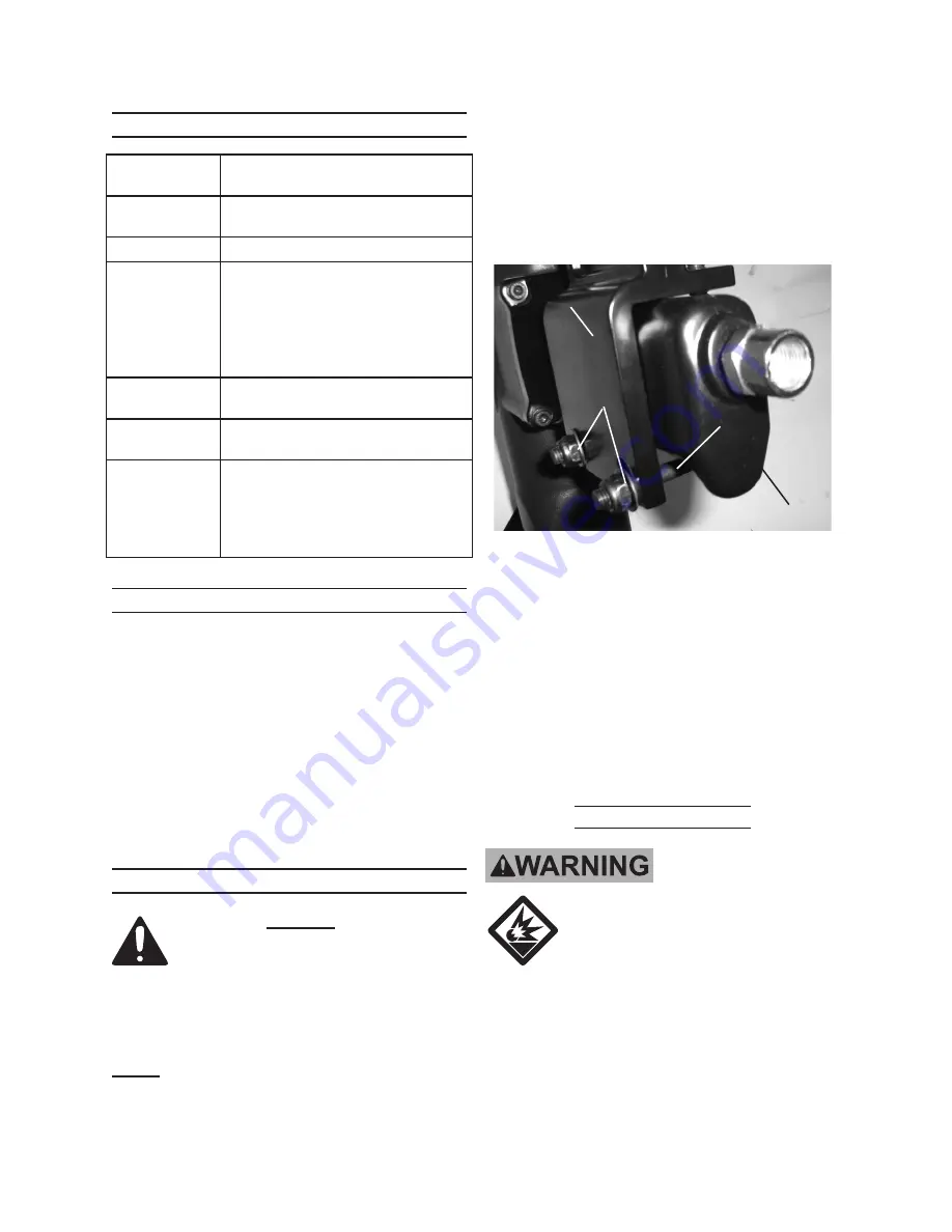
• This tool may be shipped with the 

Arm (80) detached from the main 

body.  If so, follow these instruc-

tions:

1. 

Arm (80)

Handle (69)

Bracket (72)

Nut (70) and 

Washer (71)

Figure A

Set the Arm against the Handle (69) 

and slide the Brackets (72) through 

the Arm holes slots and holes.  

Thread Washers (71) and Nuts (70) 

over ends of Brackets.   

See 

Figure A

.

2.  Wrench-tighten the Nuts until Brack-

ets are secured and the Arm is locked 

against Handle.

Air Supply Setup


TO PREVENT 

EXPLOSION: 

Use only clean, dry, regulated, 

compressed air to power tool.  

Do not use oxygen, carbon 

dioxide, combustible gases, 

or any other bottled gas as a 

power source for tool.

REV 08j; 09c; 09i

Summary of Contents for 99640

Page 1: ...l rights reserved No portion of this manual or any artwork contained herein may be reproduced in any shape or form without the express written consent of Harbor Freight Tools Diagrams within this manu...

Page 2: ...serious injury CAUTION used with the safety alert symbol indicates a hazardous situation which if not avoided could result in minor or moderate injury NOTICE is used to address practices not related t...

Page 3: ...he applicable conditions Wear heavy duty work gloves during use Wear a full face shield if you are producing metal filings or wood chips g Always wear eye protec tion Wear ANSI ap proved safety goggle...

Page 4: ...ndition that affects the tool s operation If dam aged have the tool serviced before using Many accidents are caused by poorly maintained tools There is a risk of bursting if the tool is damaged m Use...

Page 5: ...ower sanding sawing grinding drill ing and other construction activities contains chemicals known to the State of California to cause cancer birth defects or other reproductive harm Some examples of t...

Page 6: ...y a doctor and then have regular medical check ups to ensure medical problems are not being caused or worsened from use Pregnant women or people who have impaired blood circulation to the hand past ha...

Page 7: ...let Remove this plug before set up ASSEMBLY Read the ENTIRE IMPORTANT SAFETY INFORMATION section at the beginning of this manual including all text under subheadings therein before set up or use of th...

Page 8: ...y is disconnected Note Air flow and therefore tool perfor mance can be hindered by under sized air supply components 3 The air hose must be long enough to reach the work area with enough extra length...

Page 9: ...urn the switch to its off position before performing any inspection maintenance or cleaning procedures TO PREVENT SERIOUS INJURY Do not adjust or tamper with any control or component in a way not spec...

Page 10: ...g on a floor test the tool on a scrap piece of wood Adjust the driving depth by provid ing more or less air pressure Never exceed 120 PSI 5 Hold the Hand Grip 81 securely and press the Spacer 36 to th...

Page 11: ...he firing mecha nism of the Floor Nailer making the tool inoperable 5 To remove a jammed cleat nail staple disconnect the tool from its air supply push in the Lock and slide the Magazine back until it...

Page 12: ...tool oil Lubricate the internal mechanism using only white lithium grease Other lubricants may damage the mechanism and may be highly flammable causing an explosion Cleaning Maintenance and Lubricatio...

Page 13: ...sor is set between 70 PSI and 120 PSI 3 Clean exhaust channel Not shooting fasteners or only intermittent feeding 1 Damaged Pusher Spring 51 2 Wrong size of fasteners 3 Fixed Magazine 52 or Plate 45 i...

Page 14: ...ing 1 54 Safety Lock 1 55 E Ring 1 56 Pusher 1 57 Tail Cover 1 58 Washer 1 59 Hex Bolt 2 60 Spring 1 61 Side Load Magazine 1 62 Bushing 1 63 Fixture 1 64 Hex Bolt 1 65 Hex Bolt 1 66 Gasket 1 67 Spring...

Page 15: ...ord Product s Serial Number Here Note If product has no serial number record month and year of purchase instead Note Some parts are listed and shown for illustration purposes only and are not avail ab...

Page 16: ...tal or consequential damages so the above limitation of exclusion may not apply to you THIS WARRANTY IS EXPRESSLY IN LIEU OF ALL OTHER WARRANTIES EXPRESS OR IMPLIED INCLUDING THE WARRANTIES OF MERCHAN...

Reviews: